
Rotor Axial Position Sensor
 It’s an average day in the powerhouse, and suddenly the turbine starts squealing. As you’re running around trying to find the cause, the turbine gives a terrific shudder and shuts down. What you will soon discover is that the thrust bearing reached its limit of wear, sending the blades crashing into the diaphragms.
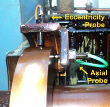
This disaster can averted by monitoring and understanding the Rotor Axial Positioning sensor. The probes of this sensor are positioned towards the collar so that the axial movement of the shaft in the direction of the generator (the usual direction of rotor thrust) will cause the gap between the probes and collar to increase. If this gap increases, it is an accurate indication that the thrust bearing Babbitt has been compromised and that the rotor is not in its proper axial position. Your I&E Engineer can determine the maximum fail-safe gap based on the minimum measured axial wheel clearance and the total thrust bearing float measurements from the last inspection (if available).
The squeal that you heard just before the machine crashed came from a “squealer ring”, which is sometimes found on older units. Similar to the fins at the end of your car’s brake pad, the ring will emit an unmistakable loud pitch sound when the machine has reached the limit of its axial thrust. If you hear this sound, immediately manually trip the unit and give us a call. Your unit is in immediate need of a major overhaul.
The axial position probes used in this modern supervisory application are proximity probes, very similar to that used in vibration systems. These probes do not contact the collar. The distance (the gap) between the collar and the probe tip is determined by the use of a high frequency magnetic field. As the rotor moves axially, the gap changes and the output signal varies proportionally. The probe tip is adjustable within the bracket assembly for an initial gap setting using a feeler gauge. This mechanical gap setting should be set by the recommended drawing specifications. However, the preferred method is to make final corrections electronically. These probes are usually set to -8.0 volts +/- 1 volt.
Some older machines use thrust trip devices that use oil pressure through a set of nozzles to a collar. These trip devices have been proven to be very reliable. This oil pressure provides a warning should the thrust bearing babbitted pads wear down to a predetermined amount. Further wear will cause the unit to trip due to the high increase in pressure. This trip takes place so that serious damage does not occur to other turbine parts.