 Direct current high voltage testing can be divided into two categories: Proof testing and Controlled Over-Voltage testing.
Proof testing qualifies an insulation system to hold a specific voltage. By definition, it is a pass-or-fail evaluation – there is no diagnostic value. Acceptance proof testing is performed on new stator winding as part of in-process and final acceptance testing. Maintenance proof testing is performed on existing equipment, typically at 75% of the Acceptance test voltage. Although proof testing is pass/fail, the microampere readings for each individual phase should be measured and recorded, and gross variations should be noted and investigated further. An initial failure may be the fault of the test setup, as high resistance leakage to the atmosphere or to ground can occur. The quality of the insulation system should be questioned only if corrections to the test setup do not result in improved test results.
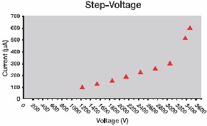
In Controlled Over-Voltage testing, the applied voltage is either “stepped-up” manually and incrementally, or “ramped-up” automatically and fluidly, over time. This provides a degree of diagnostic value since the measured current can be graphed, phase-by-phase, for comparative analysis. Controlled Over-Voltage testing affords the ability to salvage a winding that might otherwise fail in Proof testing. In plotting the measured current in real time, the operator may witness an exponential increase in current (indicating an impending insulation breakdown) and terminate the test.
DC stepped voltage and ramped voltage test results can be evaluated on a pass/fail basis, but important results can be obtained by a more thorough examination. The associated plotting might show evidence of a weakness. The higher the voltage level that presents the indication, the better the quality of the dielectric. Comparison phase-to-phase might show that one or more are comparatively high in resultant current. Most importantly, routine testing and comparatives can provide insight into the degree of insulation aging, and help predict end of useful life.
All of these tests should be performed in accordance with IEEE Standard 95™-2002, IEEE Recommended Practice for Testing of AC Electric Machinery (2300 V and Above) With High Direct Current.


 Direct current high voltage testing can be divided into two categories: Proof testing and Controlled Over-Voltage testing.