
Why Is My Generator Rotor Vibrating?
Generator rotor imbalance can come from a number of different sources, i.e. coupling misalignment, component non-concentricity, rubbing, oil issues, bearing, and journal issues. Each has unique characteristics. Thermal sensitivity has its own recognizable characteristics.
If you are unable to operate your Turbine Generator at high field current or VARs because of exceedingly high vibration, your Turbine Generator Rotor just might be thermally sensitive (with apologies to Jeff Foxworthy).

A generator is comprised of several different components, e.g. rotor body forging, copper coils, steel retaining rings, insulating slot cells, turn insulation, and creepage blocks. Each is comprised of unique materials having distinctive coefficients of thermal expansion. The differences in coefficients of the two major components, the rotor body forging and the copper coils, are significant (over 30%) and the associated forces surprisingly enormous. If these forces become restricted or otherwise unequally distributed, the rotor can develop a bend or bow. The development of temperature within a rotor is predominately a by-product of the current or amperage applied to the copper coils. This current or amperage is the source of thermal expansion and any associated thermal sensitivity.
Reversible Thermal Sensitivity:
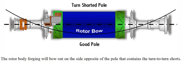
One of the most common causes of unevenly dispersed coefficients of expansion and thermal sensitivity is turn-to-turn shorts within the copper coils of a generator rotor. By their very nature, turn-to-turn shorts reduce the insulation resistance to the flow of electricity. The pole containing the shorts will actually operate at a lower temperature than its counterpart. Lower temperature equates to less thermal expansion and growth in the axial direction. The net result is a rotor body forging that bows out on the side opposite of the pole with the turn-to-turn shorts. The closer that the turn-to-turn shorts are to the pole face (say within the number-1 or number- 2 coils), the more pronounced their effect. Likewise, turn-to-turn shorts in the outer most coils (say the number-5 or number-6 coils) may have absolutely no effect on thermal sensitivity.
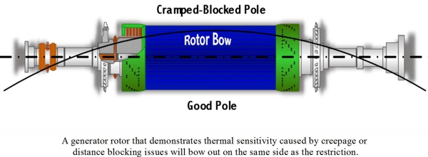
The proper installation of generator rotor end winding creepage and distance blocking is critical to proper and long term operation. Improperly installed blocking and/or blocking that has shifted out of position can cause reversible thermal sensitivity. The main windings of a rotor must be allowed unrestricted axial thermal expansion and contraction. Improperly positioned blocking can cramp or restrict this axial growth, thus causing a bow in the rotor body. A generator rotor that demonstrates thermal sensitivity caused by creepage or distance blocking issues will bow out on the same side as the restriction.

Asymmetrical thermal growth of the generator rotor coils can also be caused by excessive contamination restricting cooling or ventilation pathways. As with turn-to-turn shorts, blocked ventilation can cause uneven axial expansion as some coils operate at higher temperatures than others. The rotor will bow out on the side of the most significant ventilation restriction.
Irreversible Thermal Sensitivity:
There are a number of different conditions that cause irreversible thermal sensitivity. All have to do with restriction of the axial growth of the generator rotor main windings. All are most likely to occur after a complete rewind, partial rewind, major rehabilitation, or repair. With respect to a rotor rewind, it is critical to maintain proper winding (side-to-side) clearances. This entails ensuring that the new ground wall insulation is not too thick. It also means gauging the width of the new or existing copper to assure that it is within proper tolerances. A coil or coils wound too tight will restrict proper symmetrical axial growth and bow the rotor body. A generator rotor demonstrating this type of irreversible thermal sensitivity will bow out on the same side as the most significant restriction.
Radial symmetry must be maintained when performing either a complete or partial rotor rewind. Whether under the rotor body wedges or the retaining rings, inconsistencies in the height or buildup of the windings, coil-to-coil, can restrict the symmetrical axial growth of the rotor windings, bow the rotor body, and generate an imbalance.
![]()


If rotor body wedges are replaced, it is of absolute importance that the new wedges have the same cross-sectional dimensions as the originals. Axial restriction can take place if the new wedges are too tight in the wedge groove, or the new wedges have a deeper wedge fit to bottom face dimension.
Some generator rotor designs have only three, two, or even one wedge per slot. Such configurations are much more susceptible to wedge related irreversible thermal sensitivity. Additional safeguards must be employed when these rotor body wedges are removed to facilitate rewind or repairs. It is critical that each and every wedge be trial-fit into its exact position, and fine-tuned as required to assure proper fit.
 Testing for Thermal Sensitivity:
Operational tests can be performed in order to determine whether or not an excessively vibrating generator is thermally sensitive, and whether that thermal sensitivity is reversible or irreversible.
As stated above, a thermally sensitive TGR’s vibration will react to changes in field current. Bear in mind that a Turbine Generator’s vibration may also react to changes in megawatt loading. It is therefore important to ascertain whether excessive vibration is megawatt loading induced or field current induced.
To confirm this one needs to apply a constant field current to the TGR and then increase the megawatt load on the generator by a nominal 50% (+/-10%). Monitor generator vibration, bearing temperatures, voltage, and current. Note any change in Turbine Generator (TG) vibration readings. Maintain this level of megawatt load until all monitored operating characteristics normalize. Next, raise the TGR field current to maximum nameplate rating while maintaining the constant megawatt load.
If the TGR vibration is affected by the increase in megawatt loading, yet not affected by the field current increase, then it is not thermally sensitive. If the TGR is unable to achieve full field current due to excessive increases in vibration or if the vibration or phase angle changes significantly, then the TGR could be defined as thermally sensitive.
As the final part of the on-line test, the field current needs to be reduced to its original starting level. If the TGR vibration returns to its original level as the current is lowered then the thermal sensitivity is considered to be “reversible”. If the TGR must be brought down to turning gear, cooled, and restarted in order to regain acceptable vibration readings, then the thermal sensitivity is considered to be “irreversible”.
Thermal sensitivity can manifest itself at any point in time and for a variety of reasons. It is important that you know how to determine if your specific effects are due to thermal sensitivity, what type of thermal sensitivity you might have, and what developed this phenomena. Your TGM® Generator Specialist has the experience and expertise necessary to help.
 At STUG 2015, 50% of users of the GE D11 Steam Turbine reported cracking issues in the HP/IP shell, especially the N2 packing gland and shell fit. These cracks create the potential for forced shutdowns and relatively long outage cycle times.