Exploding Sockets Revisited

Recently, one of our sockets exploded while loosening a bolt using a HyTorc hydraulic wrench. No one was injured, but we take these incidents seriously, generating a “Near Miss” report and subsequent corrective action.

We discussed exploding sockets in a previous Safety Tip, which you can review in the May 8, 2012 post (see below). Since that post, we purchased TorcUp sockets for all our tool sets, and sprayed them yellow to make sure they were exclusively used with our HyTorc heads. One of these dedicated sockets broke under load. Please comment (below) on additional steps we can take for our corrective action.  We need your experience and expertise.

Additional information: The broken socket was less than a year old.  It was a 1” drive, 1 5/8” 12 point socket under an 8000 PSI load.  We chose TorcUP sockets as they were the middle of the road in pricing of the three vendors we reviewed (one was HyTorc).

All of us face similar safety concerns in our operations. If you would like one of your concerns discussed in this forum, please contact us via Mr. Turbine (click here) and we will start the conversation in our next newsletter. We will not share your contact info but you can also post anonymously.  Mr. Turbine will be happy to give an immediate response if you request it, but of course we must have your correct info.

Polarization Index (PI) Test

A Polarization Index (PI) test is generally performed at the same voltage as the Insulation Resistance (IR) test.  Where the IR test is performed for a period of one minute, the PI test is performed over a period of ten minutes. This gives the absorption (polarization) current ample time to decay, and reveals a more detailed indication of the total leakage and conduction current. As such, PI is a good indication of winding contamination, moisture ingress (leakage currents), and/or bulk insulation damage (conduction currents).
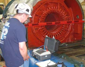
Polarization Index testing is generally performed with an Insulation Resistance (IR) test set (commonly known as a Megger), immediately after performing the IR test. However, the test can also be performed utilizing a DC high potential (hipot) test set. The readings produced by the two instruments are different. A Megger commonly gives readings in ohms of resistance. A hipot registers the amount of current (typically in microamps (mA). One microamp is equal to 1 x 10⁻⁶ amps, or 0.000001 amps.

The Polarization Index is derived by the ratio between the one minute reading and the ten minute reading. Recommended minimum PI results for suitability for service (or implementation of high voltage testing) is widely accepted as 2:1 or greater. Any reading lower than this minimum value is a concern. The windings would be presumed to be wet, contaminated, and/or compromised in some fashion. Conversely, vintage windings (varnish cambric, asphalt mica, etc.) may produce an unusually high Polarization Index ratio.  The insulation may be void of binder content, thus making it dry and brittle.  According to IEEE standards, if the insulation resistance reading after the voltage has been applied for one minute is greater than 5,000 megohms the resulting polarization index may or may not be indicative of the true insulation condition and is therefore not recommended as a means of assessment.

Polarization Index testing should be performed in accordance with IEEE Standard 43-2000(R2006), IEEE Recommended Practice for Testing Insulation Resistance of Rotating Machinery. A Megger brand model number BM25 (or its replacement or comparable) is recommended if a Megger is used. A High Voltage, Inc. PTS Series DC high potential test set is recommended if a hipot is used.

Proper Manual Lifting

Back pain constitutes about 10% of occupational injuries and is the most common reason to take leave from work.  Each year about $50 billion is spent on treatment in The U.S. alone, making it the third most expensive condition after heart disease and cancer. With this in mind, an ounce of prevention is worth a pound of cure (pun intended). Before lifting an object of unknown weight, perform several trial lifts using gradually increasing effort.  Do not attempt to lift an object that you cannot confidently handle. Always identify the path you will be taking with the load and clear away all obstacles. Use proper gear for every lift. Wear shoes with good traction and solid gripping gloves which will help you to hold the object for a longer period of time.

Avoid standing too far from the load as it might not provide you the needed grip to hold the object properly. Align yourself properly over the load with your feet and shoulders wide apart. This will give you the exact balance needed to hold the load while lifting it. Never bend at the waist and lift an object with your back. Keep your upper body straight and parallel with your lower legs. Grab the item and push up with your legs, not with your back. Never rotate or twist your body while lifting. Keep your head up when handling the load. Look ahead, not down at the load once it has been held securely. Make sure you lift with a slow, steady force. This will help you avoid muscle strains from having to counter an unbalanced load. Take smooth and small strides to avoid muscle strain from overcompensating for shifting loads. For heavier loads, try lifting with your full breath, and tighten your abdominal muscles for added support. For long lifts, such as from floor to shoulder height, consider resting the load mid-way on a table or bench to change your grip on it.  Always use a lifting belt or back brace if preforming multiple lifts. Don’t lift or handle more than you can easily manage. There’s a difference between what people can lift and what they can safely lift. If at all possible, get help.  Lift with a buddy or use a mechanical lifting device such as a crane, chain fall or a jack.

Insulation Resistance (IR) Test

The Insulation Resistance Test measures the integrity of the generator’s winding insulation, and therefore the likelihood of developing a ground.  A test voltage is applied to the generator and the current flow required to maintain that voltage is measured over a period of time (typically one minute).  In simplest terms, the less current flow, the higher the resistance value, and the better the insulation.

An IR test should be performed immediately following any type of event that is suspected of over-stressing an insulation system, prior to the generator being placed back into service. This is the first test that should be performed. The results will indicate the ability of the insulation system to withstand  any more searching and/or strenuous testing. The IR test also measures the effect of contamination from water, oil, carbon, and other such undesirables. If a separate high voltage proof test is performed, an IR test should be performed both before and after the proof test. This in order to assure that the proof test itself has not compromised the insulation.

The Insulation Resistance test must be performed by a well trained and experienced technician.  Incorrect procedures can materially affect the results. The test should be performed to IEEE Standard 43-2000 (R2006), using a late model Megger brand machine such as Model MIT1025, or comparable.  It is best practice to test at the main and neutral leads of the stator, as close to the windings as possible.  Stator slot RTD’s should be disconnected from the terminal board and grounded. Surge capacitors should be disconnected.  The water or oil should be drained and completely evacuated from liquid inner-cooled windings, typically by vacuum-processing. Stator windings should be tested one phase at a time, with the other two phases grounded. In this manner, the windings are stressed both phase-to-ground and phase-to-phase.

The results should be interpreted by an experienced technician. Your final report should reflect that environmental conditions and even the age and configuration of the machine were taken into consideration.

If you have any questions concerning the application of this test or the interpretation of the results, please contact Mr. Turbine.