Generator Field Journal Machining
We recently completed a Journal Machining project on a Generator Journal. It cleaned up nicely and the customer was very satisfied with the end result. Great job by our machining team!
 |
 |

We recently completed a Journal Machining project on a Generator Journal. It cleaned up nicely and the customer was very satisfied with the end result. Great job by our machining team!
|
|
We were recently hired to machine and re-groove a set of collector rings on a 7FH2 Generator. This is a common service we perform during outage seasons when turbine generator outages are taking place and customers inspect the current condition of their collector rings and check groove depth. When it is noted that the collector rings need machining and/or re-grooving we are contacted to bring in specialty equipment and experienced personnel to perform these repairs on-site. The collector ring grooves and surfaces are machined, bringing the component back to within acceptable specifications. If you are ever in need of collector ring machining and/or re-grooving please give us a call. We’ll tool up and mobilize immediately and ensure we provide you with a safe, quality, efficient performance. For more information regarding our generator collector ring repairs, see our line card HERE.
As Found

Re-grooved

After Machining

During any turbine generator outage season we often receive an influx of calls to perform collector ring machining on various makes and models of generators. It is critical to maintain as much brush to collector ring contact as possible, and machining the rings can make sure the surface is free from defects that may inhibit brush to ring contact. The need for this machining is typically determined after the generator has been disassembled and inspected, making this service an emergent repair that needs to be performed within a time-sensitive window. When these requests are received we typically request basic dimensional data and then provide a quick quotation for services. Once approved, we immediately dispatch our qualified technicians to site along with specialized machining equipment. This work is typically completed in 1-2 shifts, and the customer is able to continue forward without this service having any impact on the overall schedule.
Before

After

Generator rotor imbalance can come from a number of different sources, i.e. coupling misalignment, component non-concentricity, rubbing, oil issues, bearing, and journal issues. Each has unique characteristics. Thermal sensitivity has its own recognizable characteristics.
If you are unable to operate your Turbine Generator at high field current or VARs because of exceedingly high vibration, your Turbine Generator Rotor just might be thermally sensitive (with apologies to Jeff Foxworthy).

A generator is comprised of several different components, e.g. rotor body forging, copper coils, steel retaining rings, insulating slot cells, turn insulation, and creepage blocks. Each is comprised of unique materials having distinctive coefficients of thermal expansion. The differences in coefficients of the two major components, the rotor body forging and the copper coils, are significant (over 30%) and the associated forces surprisingly enormous. If these forces become restricted or otherwise unequally distributed, the rotor can develop a bend or bow. The development of temperature within a rotor is predominately a by-product of the current or amperage applied to the copper coils. This current or amperage is the source of thermal expansion and any associated thermal sensitivity.
Reversible Thermal Sensitivity:
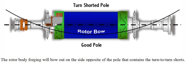
One of the most common causes of unevenly dispersed coefficients of expansion and thermal sensitivity is turn-to-turn shorts within the copper coils of a generator rotor. By their very nature, turn-to-turn shorts reduce the insulation resistance to the flow of electricity. The pole containing the shorts will actually operate at a lower temperature than its counterpart. Lower temperature equates to less thermal expansion and growth in the axial direction. The net result is a rotor body forging that bows out on the side opposite of the pole with the turn-to-turn shorts. The closer that the turn-to-turn shorts are to the pole face (say within the number-1 or number- 2 coils), the more pronounced their effect. Likewise, turn-to-turn shorts in the outer most coils (say the number-5 or number-6 coils) may have absolutely no effect on thermal sensitivity.
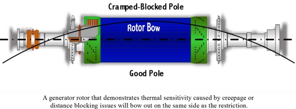
The proper installation of generator rotor end winding creepage and distance blocking is critical to proper and long term operation. Improperly installed blocking and/or blocking that has shifted out of position can cause reversible thermal sensitivity. The main windings of a rotor must be allowed unrestricted axial thermal expansion and contraction. Improperly positioned blocking can cramp or restrict this axial growth, thus causing a bow in the rotor body. A generator rotor that demonstrates thermal sensitivity caused by creepage or distance blocking issues will bow out on the same side as the restriction.

Asymmetrical thermal growth of the generator rotor coils can also be caused by excessive contamination restricting cooling or ventilation pathways. As with turn-to-turn shorts, blocked ventilation can cause uneven axial expansion as some coils operate at higher temperatures than others. The rotor will bow out on the side of the most significant ventilation restriction.
Irreversible Thermal Sensitivity:
There are a number of different conditions that cause irreversible thermal sensitivity. All have to do with restriction of the axial growth of the generator rotor main windings. All are most likely to occur after a complete rewind, partial rewind, major rehabilitation, or repair. With respect to a rotor rewind, it is critical to maintain proper winding (side-to-side) clearances. This entails ensuring that the new ground wall insulation is not too thick. It also means gauging the width of the new or existing copper to assure that it is within proper tolerances. A coil or coils wound too tight will restrict proper symmetrical axial growth and bow the rotor body. A generator rotor demonstrating this type of irreversible thermal sensitivity will bow out on the same side as the most significant restriction.
Radial symmetry must be maintained when performing either a complete or partial rotor rewind. Whether under the rotor body wedges or the retaining rings, inconsistencies in the height or buildup of the windings, coil-to-coil, can restrict the symmetrical axial growth of the rotor windings, bow the rotor body, and generate an imbalance.
![]()


If rotor body wedges are replaced, it is of absolute importance that the new wedges have the same cross-sectional dimensions as the originals. Axial restriction can take place if the new wedges are too tight in the wedge groove, or the new wedges have a deeper wedge fit to bottom face dimension.
Some generator rotor designs have only three, two, or even one wedge per slot. Such configurations are much more susceptible to wedge related irreversible thermal sensitivity. Additional safeguards must be employed when these rotor body wedges are removed to facilitate rewind or repairs. It is critical that each and every wedge be trial-fit into its exact position, and fine-tuned as required to assure proper fit.
 Testing for Thermal Sensitivity:
Operational tests can be performed in order to determine whether or not an excessively vibrating generator is thermally sensitive, and whether that thermal sensitivity is reversible or irreversible.
As stated above, a thermally sensitive TGR’s vibration will react to changes in field current. Bear in mind that a Turbine Generator’s vibration may also react to changes in megawatt loading. It is therefore important to ascertain whether excessive vibration is megawatt loading induced or field current induced.
To confirm this one needs to apply a constant field current to the TGR and then increase the megawatt load on the generator by a nominal 50% (+/-10%). Monitor generator vibration, bearing temperatures, voltage, and current. Note any change in Turbine Generator (TG) vibration readings. Maintain this level of megawatt load until all monitored operating characteristics normalize. Next, raise the TGR field current to maximum nameplate rating while maintaining the constant megawatt load.
If the TGR vibration is affected by the increase in megawatt loading, yet not affected by the field current increase, then it is not thermally sensitive. If the TGR is unable to achieve full field current due to excessive increases in vibration or if the vibration or phase angle changes significantly, then the TGR could be defined as thermally sensitive.
As the final part of the on-line test, the field current needs to be reduced to its original starting level. If the TGR vibration returns to its original level as the current is lowered then the thermal sensitivity is considered to be “reversible”. If the TGR must be brought down to turning gear, cooled, and restarted in order to regain acceptable vibration readings, then the thermal sensitivity is considered to be “irreversible”.
Thermal sensitivity can manifest itself at any point in time and for a variety of reasons. It is important that you know how to determine if your specific effects are due to thermal sensitivity, what type of thermal sensitivity you might have, and what developed this phenomena. Your TGM® Generator Specialist has the experience and expertise necessary to help.
 A generator is susceptible to four categories of aging factors which reduce the overall service life of the machine: 1) Mechanical aging; 2) Thermal aging; 3) Electrical aging; 4) Environmental aging. Simply stated, a dirty (contaminated) generator causes environmental aging. A few of the more common contamination elements include oil, water, dirt, dust, carbon, and fly ash. Environmental aging factors will facilitate the other three aging mechanisms as well. Examples: 1) Mechanical aging – the integrity of a stator winding may loosen and degrade as binders in the epoxies and varnishes are broken down by solvents and chemicals. 2) Thermal aging – Insulation systems throughout a generator will break down if contaminates build-up and block-off ventilation passageways such that thermal classification limits are exceeded. 3) Electrical aging – Phase-to-ground and/or phase-to-phase flashovers may occur between two dielectric weak points sufficiently bridged by a conductive coating of contaminates.
The two most common and virulent contaminates are water and oil. Each of these two materials act as an adhesive that binds particulates into a buildup across surfaces throughout a generator. This is especially true of air-cooled machines. Also, water is a conductor of electricity. The ramifications of its presence need no explanation.
Oil contamination is undesirable for two additional reasons. First, it is a lubricant. Electrical windings, and in particular stator windings, are held tightly together through a number of frictional forces. Side packing holds the stator windings tightly within the stator slots side-to-side. The wedge system holds the stator windings radially within the same slots. Hundreds of blocks and miles of lacing secure the stator end windings to one another as well as to surge rings and brackets. Oil contamination leaches in between all these components. Its lubricating qualities facilitates looseness and mechanical fretting. Second, oil is a mild solvent. Over time it will break down the organic binders in paints, varnishes, and even modern epoxies. Degradation of these materials reduces the dielectric strength of the ground wall insulation system and accelerates electrical aging. Oil’s solvent and lubrication properties contribute to mechanical aging by impairing the homogeneous and monolithic character of the stator winding. Oil contamination must be eliminated (to the best degree possible) to ensure the long-term serviceability of a generator. More importantly, the source of the leakage must be remediated.
Opinions vary regarding proper cleaning materials and methodologies. However, it should be considered as best practice to define a cleaning protocol based upon: 1) Type of contamination; 2) Degree of contamination; 3) Type of insulation system, and; 4) Condition/disposition of the insulation system. Cleaning may include simple wipe down, solvent spraying, dry ice blasting, dry media blasting (corn cob, walnut shell, etc.), steam cleaning, or some combination. Positives and negatives are associated with each and should be discussed prior to implementation.
Simply stated, a clean generator is a happy generator. A consistently clean generator runs cooler, stays mechanically-robust longer, and is significantly less prone to electrical tracking and flash-over failure. A clean generator demonstrates superior operation and maintenance practices and helps assure quality service life. How clean is your generator?

 A generator is a device that converts mechanical energy into electrical energy. According to the concept of energy conservation, all mechanical energy that is introduced into the generator is converted into useful energy (electricity) or useless energy (primarily heat). The efficiency of a generator is based upon the ratio of useful to useless energy. As generators have grown in size and capacity through the years so has the need to improve efficiency through minimizing heat.
Hydrogen was first proposed as a cooling media for rotating electrical machinery in 1925. The first hydrogen-cooled machine, a 12.5 MVA synchronous condenser, was placed into service in 1928. Nearly a decade later, in 1937, the first hydrogen-cooled turbo generator was commission by Dayton Power and Light in Dayton, Ohio – a General Electric 31.25 MVA, 3,600 RPM unit. Coincidently, this was the very same year that the German passenger zeppelin, Hindenburg, met with its fiery demise.
So why use hydrogen to cool a generator? Despite its reputation, hydrogen gas has qualities that make it a superior heat transfer media and internal atmosphere for a generator. Hydrogen is much less dense that air. Cooling fans can move up to fourteen (14) times as much hydrogen as air using the same amount of power. Combine this with the fact that hydrogen conducts seven (7) times more heat than air. At the same time, hydrogen has a higher heat transfer coefficient; meaning it is better at picking up heat from a hot surface. Hydrogen also has approximately the same specific heat characteristic as air, since they both can carry about the same amount of heat.
| Properties of Hydrogen | |||
| Characteristic | Air | Hydrogen | What This Means |
| Density | 1.00 | 0.07 | A cooling fan can move 14 as much hydrogen as air, using the same amount of power |
| Thermal Conductivity | 1.00 | 7.00 | Hydrogen conducts heat 7 times better than air |
| Heat Transfer Coefficient From Surface To Gas | 1.00 | 1.35 | How well the medis picks up heat from a hot surface |
| Specific Heat | 1.00 | 0.98 | How much heat the media can hold |
| Support of Combustion | Yes | No | Does the gas help fire burn? |
| Oxidizing Agent | Yes | No | Does the gas support rusting? |
Hydrogen does not support combustion. It only becomes volatile when mixed with air. What makes the mixture so deadly is the breadth of its explosive range – from as little as 4-percent to as much as 74-percent. The potential energy release from a hydrogen-fueled explosion is enormous:
| Potential Energy in Hydrogen | |
| One (1) standard portable cylinder | 35 pounds of TNT |
| A twelve (12) pack of cylinders | 420 pounds of TNT |
| One (1) standard tube trailer | 5.585 pounds of TNT |
Due to the volatility of hydrogen gas, the power generation industry employs tried and true procedures for its monitoring, handling, and disposition. Fires and explosions do occur, though their frequency is miniscule in comparison to the sheer number of hydrogen-cooled generators in operation and the vast quantities of hydrogen handled on an annual basis. The positives far outnumber the negatives. Hydrogen has been an internal cooling media of choice for the last eighty years and will continue to be so for the foreseeable future.
 A turbogenerator stator is comprised of two major components: 1) the stator windings, and 2) the stator core. The stator core is made up of thousands, tens of thousands, or hundreds of thousands of individual steel laminations. Modern laminations are comprised of silica-steel, cold-rolled and grain-oriented as specific designs might require. The material is typically between 0.014″ to 0.018″ (29 to 26 gauge) thick and coated with a very thin layer of insulation, as little as 0.001″ thick.
Stator core laminations have a very specific profile and the dimensions have exacting tolerances. Currently, laminations are manufactured by Punching/stamping dies, or Computer-controlled laser cutting machines.

 A stator core is built up as laminations are placed side-by-side in order to make a complete circular or ringed layer. The next layer is laid, offsetting each layer like a brick or cinder block wall. A stator core can easily be ten to twenty feet in length, at 0.014″ to 0.018″ per layer. It is no wonder that thousands of individual laminations are required. This enormous mass of steel segments is aligned and held together under compressive load with components such as key bars, building bolts, through bolts, finger plates, and compression rings.
An energized turbine generator rotor creates an electromagnetic field with lines of force traveling from north pole to south pole very much like that of planet Earth.

 As the energized rotor rotates within the stator core, these lines of force travel through layers of laminations in a tangential direction. According to the laws of electromagnetism, a perpendicular magnetic field is created as a current flows through a conductor. Conversely, as the magnetic field of our energized rotor passes through our stator core, it creates a perpendicular flow of current through the stator. If our stator core were made from one solid piece of steel, these currents (known as circulating currents or eddy currents) and the associated heat generated would be huge. So huge in fact that the generator core would quite conceivably melt down. The circulating currents are reduced to a significantly smaller and more controllable size by laminating the core iron and insulating each layer from the others. The heat created by the currents can then be managed by pumping cooling gasses (air or hydrogen) across and/or through the core iron structure.
This same principle applies in other applications. Anyone who has used a common induction bearing heater will have noticed that the cross bar is fabricated of laminated (and insulated) steel. During the process of induction heating, the bearing heats up quite quickly while the cross bar stays relatively cool.
Simply stated a stator core is laminated and insulated in order to reduce induced circulating currents and associated heat down to a manageable level.

 TGM® has developed a process to install a magnetic flux probe without removing the rotor from the generator. A flux probe can detect the degree and location of shortened turns in generator rotor windings, down to a specific pole and coil, without taking the generator off line. An installed flux probe allows generator specialists to monitor the accumulation of these shorts and develop remediation plans and timelines to forestall load degeneration or forced outages.
Shorts are commonly caused by the dielectric breakdown of the turn-to-turn insulation system within the main field windings. This failure can result from movement and fretting of the conductors caused by coil foreshortening, end-strap elongation, or inadequate end-turn blocking. Metal particles from erosion or rubbing (copper dusting) can also form new and undesirable pathways between turns.
The magnitude and location of turn-to-turn shorts play heavily in whether or not they will even be noticed. Indeed a great many shorted rotors have operated without issue for years. It is those rotors with turn shorts nearest the poles that are most likely to become thermally sensitive; this caused by asymmetrical heating, rotor bowing, and associated vibration. Shorts can also produce unbalanced magnetic forces, which will increase mechanical stresses. This combination of thermal and mechanical stresses can create more shorts and an accelerating pattern of degradation. On-line monitoring can measure this degradation and signal the increasing need for remediation before a forced outage occurs.
 Previously, the rotor had to be removed to gain access to install a flux probe. TGM® has developed special tooling and procedures for installing flux probes with the rotor in place. Placement of the probe is no easy task. Imagine installing an instrument several inches inside the generator air-gap, under conditions so restrictive that you cannot even reach in and touch the inboard side of the retaining ring. TGM® has developed a pneumatically actuated device which inserts the flux probe sensor into the air-gap and presses the sensor against the top of the core iron tooth. The pneumatic tool expands, using the OD of the rotor as a backstop and holds the flux probe in position while the epoxy cures. Amazing and ingenious.
For more information, or for a proposal to install a flux probe in your generator, please contact your TGM® Regional Account Manager at 800-226-7557
 General. The typical generator stator winding consists of three independent circuits or phases. These circuits must be as symmetrical as possible with one another to achieve maximum generator efficiency. This symmetry includes the cross section of each conductor as well as the length or distance from main lead to neutral lead. The Copper Resistance (or Winding Resistance) test measures this “distance” for proper length and high resistant anomalies (i.e. cracks, shorted turns, open circuits, etc.). An increase in resistance from one test to another could indicate the potential for a future winding failure.
Test Setup & Execution. The main and neutral lead connections should be broken and open. The lead ends should be free and clean of surface contamination so that the test probes make good contact. Copper resistance testing is performed with a Digital Low Resistance Ohm Meter (DLRO) test set. The DLRO instrument is extremely sensitive. Poor contact and circuit set-up can either produce erroneous readings or no readings at all.
One probe of the DLRO is connected to one lead of an individual phase, and the other probe connected to the other lead of the same phase. A reading (generally to the fourth decimal place) in ohms resistance is measured and recorded. This same process is repeated on the second and third phase. The ambient air temperature and humidity should be recorded as well.
Interpretation of Results. Temperature significantly influences the resistance of a dielectric as well as a conductor. For this reason, the copper resistance measurement should be corrected to standard (typically 40°C).
The original equipment manufacturer normally records and documents the as-built phase-by-phase copper resistance measurements. These are used as the baseline by which all future readings can be compared.
An increase in in copper resistance indicates the presence of some form of high resistance issue (i.e. broken conductors, cold braze joints, turn-to-turn shorting, incorrect connection, incorrect number of turns or stranding, open circuit). Additional testing will be required to determine the specific cause of the variant reading.
Standard. IEEE Standard 11 8TM-1 978, IEEE Standard Test Code for Resistance Measurement.
Test Equipment. A Megger, Model DLRO-10 or comparable is recommended. Kelvin and Wheatstone bridges are also used to measure resistance.
Which is better: AC or DC Testing? Will these tests hurt my generator? Here are the facts:
In conclusion, AC high potential testing is better suited for acceptance proof testing of new equipment (i.e. coils, bars, and stator windings). DC testing is better suited for in-process proof testing, maintenance proof testing, and controlled over-voltage testing of new and/or used equipment. AC or DC high potential testing should not be used as the sole source of diagnostic or acceptance data. An experienced and qualified generator testing specialist will recommend a testing protocol specifically suited to your machine’s life cycle and operating history.
* A one minute AC or DC high potential test equates to approximately 11 hours of useful life expended. Assuming that a stator winding has a nominal 30-year life expectancy (263K hours), this would equate to only a 0.0004% reduction in service life per test.