
Casing Repair – Cracking
This is Part One of a three part Turbine Tip series, discussing the most common steam turbine casing problems: cracking, distortion and erosion.
Most units can be repaired by grinding, welding or by pre-stressed mechanical methods. Finite element calculations show that in many cases, repairs can overcome some of the original design weaknesses and extend useful life by up to 20 years. But before proceeding with a repair, understand the mechanisms of both the casing damage and the proposed repair. Improper repair can be useless or worse.
Cracking is the most common problem on utility units built before 1970. Cracking typically occurs at the steam inlet areas on the HP and IP sections, where transient thermal stresses can exceed the yield point of the casing material. Cracking may be found on the interior surfaces of steam chests, valve bodies, nozzle chambers, seal casings, diaphragm fits and bolt holes.
 In the low pressure section (LP) cracking can also occur at the inlet sections, inner casings, support struts, bolt holes and diaphragm fits. Computer modeling and advanced alloys have reduced the likelihood of cracking in more modern units, but cracks can develop in any unit, especially those experiencing more stop/start cycles.
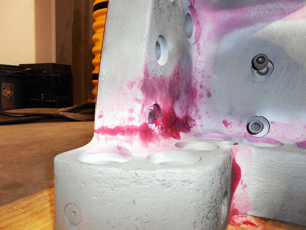
Every crack must be fully analyzed before attempting repairs and NDE inspection must be performed at a minimum. Radiograph inspections may provide greater assurance by revealing the extent of the crack in relation to its location and the thickness of the surrounding area. Some OEM’s have a detailed customer letter on known areas of potential cracking, their particular process to map out these cracks, and the proposed corrective action and potential life expectancy.
Although grinding is a common repair method, it can increase the potential for new cracks if improperly applied. Cracks in steam chests can potentially expand, making repairs more costly. Grinding on cracks in older machines may reveal voids in the casing, making the condition much worse.
Another problem is that even when an NDE shows that cracks have been removed by grinding, very small undetectable cracks may still be present and may lead to future larger cracks.
Welding of cracks is another common repair method. There are two distinct procedures for welding: stress relieved and non-stress relieved. Non-stress relieved weld repair has the advantage of shorter outage duration but can fail much sooner than a stress relieved weld. This complicated topic will be discussed in our next Turbine Tip in the series.
Mechanical Repairs can be applied to cracks, but must be properly designed to redistribute tensile loading away from the crack area. One method is to apply stitches across the crack. Another method is to place bars or dog bone shapes across previously ground out areas.
A more effective method uses precision machining and the application of a lobe-lock designed through finite element analysis. The material properties of the lobe-lock must be such that it provides maximum pre-load at a certain temperature and a reduced pre-load at that same temperature. The material must also be ductile at all temperatures to prevent cracking of the lobe-lock.
Mechanical repairs have several advantages. The repairs can be performed in place, with no possibility of casing distortion because there is no heating or welding. Machining durations are shorter and easier to quantify. These repairs can also extend life to the area (vs. welding).
A potential disadvantage is that the mechanical repair is conducted on a low cycle fatigue crack and concentrated in an area surrounded by non-cracked material.