Casing Repair – Distortion and Erosion

This is Part Three of a three part Turbine Tip series, discussing the most common steam turbine casing problems: cracking, distortion and erosion.

The final Turbine Tip in this series discusses two common steam turbine casing problems – Distortion and Erosion. The repair methods employed – grinding, mechanical repair, welding and stress relief – have their own set of considerations which were covered in previous portions of the series.

Casing Distortion becomes a strong likelihood when the units accumulate operating cycles. The most common causes of distortion are steady state and transient thermal stresses which can occur within all turbine sections (HP, IP, LP). Inner casings distort more easily than outer casings due to their thinner cross-section and higher temperature differentials across the casing walls.

Casing Repair – Distortion and Erosion Turbine Tips6Distortion typically causes problems during disassembly and reassembly. Some examples of this are bolting interferences, gaps at the horizontal joint, galling of the fits and misalignment of the steam path seals. These problems can lead to steam leakage and rubbing. Internal leakage due to distortion reduces efficiency and power output, while leakage to atmosphere and internal rubbing can both cause a forced outage.

Water induction can cause extreme distortion of the inner cylinders. This can damage internal steam path components and lead to forced outages. Inner casings as well as valve bonnet covers can become severely warped and may require extreme measures to remove and replace.

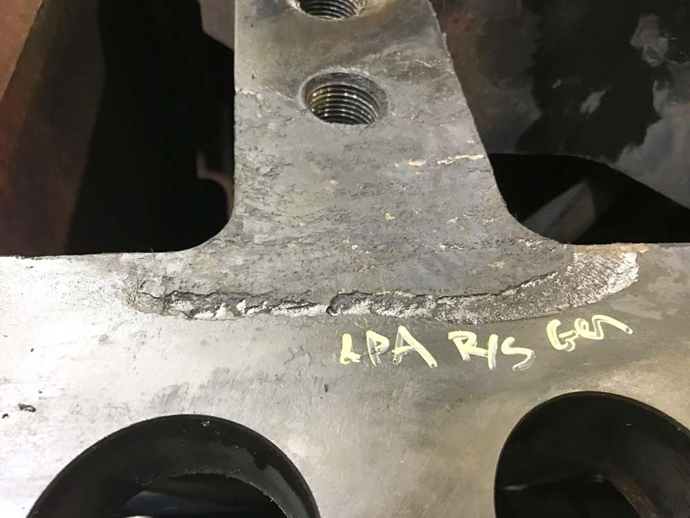
Casing distortion can be corrected by welding, machining, localized heating and rounding discs inserted during stress relief. See previous Tips in the series for considerations in employing these methods.

Damage from erosion affects different designs at different locations, but both rotating and stationary components are vulnerable. Erosion typically takes place in the LP section where steam enthalpy drops below the saturation point. Crossover pipes and inlet areas to the LP section could increase in roughness as the surfaces wear unevenly. Support struts may thin or be cut through.

Moisture erosion can also take place in the exhaust ends of HP and IP sections if the turbine operates for long periods at low load or goes through frequent start-ups. Horizontal joints may erode and leak between stages and stationary blade support rings may erode as well as crack.

Casings, diaphragms, hoods and crossovers are usually made of carbon steel or cast iron. These materials erode approximately 20 times faster than blading material made out of 400 stainless steel.

Erosion can contribute to major damage. Repairs must be aimed at improving the erosion resistance of the steam path and support surfaces. Methods also must be examined for reducing steam moisture content and the size of droplets.

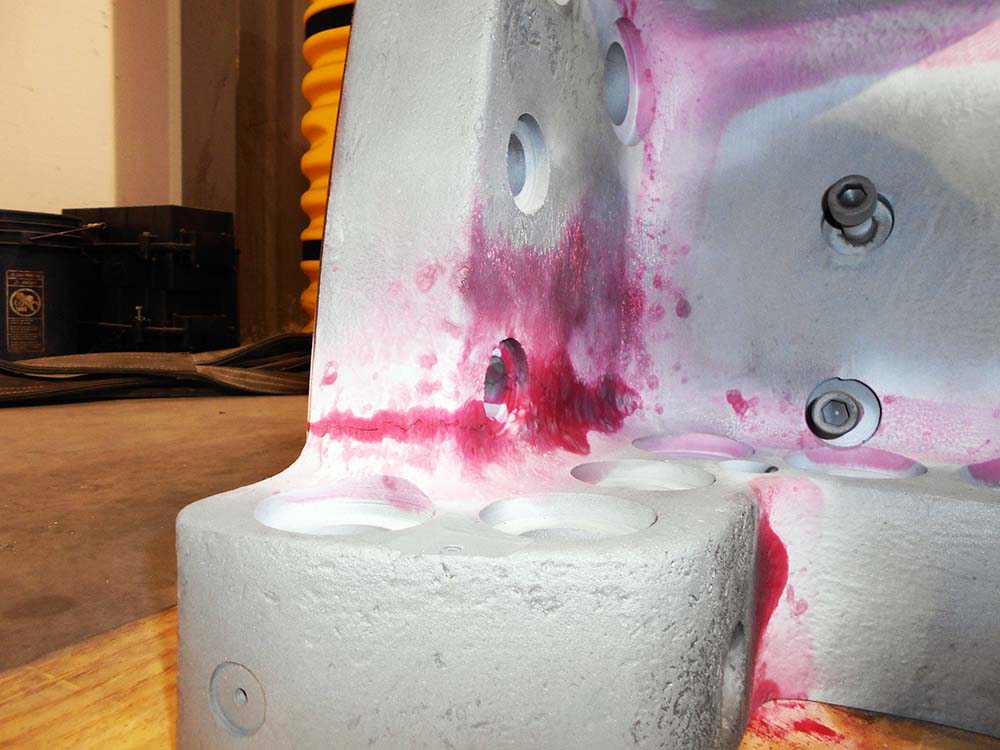
Eroded areas can be rebuilt. Stainless steel or other erosion resistant weld metal can be applied to eroded seal surfaces such as horizontal joints, flow guides and diaphragm inner and outer rings and joints. Fabricated stainless steel liners can be welded inside of crossovers, seal areas and inlet flow areas of casings. They may also be applied over support struts to protect the existing cast iron, steel or low alloy castings.

No stress relief is required in most welding applications. Epoxy or ceramic coatings may be suitable for surfaces that are not suitable for weld overlay.

For more information on your particular application, please contact us at (864) 671-1443 .

This concludes our Turbine Tip series, but we invite you to continue reading our PSG blog for more useful information.

Casing Repair – Welding Considerations

This is Part Two of a three part Turbine Tip series, discussing the most common steam turbine casing problems: cracking, distortion and erosion. 

Welding is a common method to repair turbine casing cracks, but it must be applied with consideration. Most turbine casing alloys can be welded using either of two distinct procedures: stress relieved and non-stress relieved. The procedure selected is often dictated by time and cost restraints.

Non-stress relieved welds have the advantage of lower cost and shorter outage time.  The disadvantage is that the weld can be short lived.  The procedure follows this outline: A preheat of about 500 degree F or greater is used. A shielded metal arc weld is performed with a non-matching high nickel content filler.    This use of dissimilar metals as filler can lead to low cycle metal fatigue.  No post-weld stress relief is performed but the preheat conditions are maintained throughout the process.

Casing Repair – Welding Considerations Turbine TipsStress relieved welding offers the best potential for a long repair life, but is complicated and time consuming.  The procedure follows this outline: A lower preheat of about 300 degree F is used. A shielded metal arc or metal inert gas weld is performed with a matching metal content filler. The casing is then placed in a furnace and raised to a temperature of over 1,000 degrees F.  The exact temperature depends on the alloy, the procedure and the application.  Much higher temperatures may be required. There are no problems with differential expansion during turbine operation since the weld uses matching filler metal.

The pre-weld residual stress levels in the casing must be carefully assessed to increase the probability of a successful weld.  The high levels of residual stresses in the casing can combine with the added stresses of welding to cause uncontrolled distortion and hot cracking during the stress relief phase. Residual stresses generated by the weld passes can be reduced through techniques such as grinding, peening between passes, and peening and grinding. Therefore, the welding procedure must be performed by a skilled contractor.

The best way to control distortion during stress relief is to bolt the casing halves together and place the assembly in the furnace.  This would be most applicable to an inner casing that can be easily removed from its outer casing.  If only the upper half of the casing is going to be repaired, a thick plate can be bolted onto the horizontal joint as a substitute for the lower case. Distortion can be further controlled by inserting custom fabricated rounding rings or disks into the assembly before  thoroughly bolting it together.

If the facility has ample room, a portable furnace can be built on-site.  Otherwise, the assembly must be sent out for this process.  If the assembly is too large for the furnace, stress relief can be done on a local area of the case, allowing suitable temperature gradients away from the weld areas. Whatever the location, the temperature of the furnace and the assembly must be stringently monitored during the entire stress relief process.

Multiple heat cycles and possible re-tightening of the joint bolting between cycles may be necessary. This is a process which has been refined over the years and continues to get better.  Again, it is always a good practice to perform an assessment prior to performing any of the above procedures.

The next Turbine Tip in the series discusses Distortion and Erosion in casing repair.

Casing Repair – Cracking

This is Part One of a three part Turbine Tip series, discussing the most common steam turbine casing problems: cracking, distortion and erosion.

Most units can be repaired by grinding, welding or by pre-stressed mechanical methods.  Finite element calculations show that in many cases, repairs can overcome some of the original design weaknesses and extend useful life by up to 20 years. But before proceeding with a repair, understand the mechanisms of both the casing damage and the proposed repair.  Improper repair can be useless or worse.

Cracking is the most common problem on utility units built before 1970.  Cracking typically occurs at the steam inlet areas on the HP and IP sections, where transient thermal stresses can exceed the yield point of the casing material.  Cracking may be found on the interior surfaces of steam chests, valve bodies, nozzle chambers, seal casings, diaphragm fits and bolt holes. 

Casing Repair Cracking Turbine TipIn the low pressure section (LP) cracking can also occur at the inlet sections, inner casings, support struts, bolt holes and diaphragm fits. Computer modeling and advanced alloys have reduced the likelihood of cracking in more modern units, but cracks can develop in any unit, especially those experiencing more stop/start cycles.

Every crack must be fully analyzed before attempting repairs and NDE inspection must be performed at a minimum.  Radiograph inspections may provide greater assurance by revealing the extent of the crack in relation to its location and the thickness of the surrounding area. Some OEM’s have a detailed customer letter on known areas of potential cracking,  their particular process to map out these cracks, and the proposed corrective action and potential life expectancy.

Although grinding is a common repair method, it can increase the potential for new cracks if improperly applied. Cracks in steam chests can potentially expand, making repairs more costly.  Grinding on cracks in older machines may reveal voids in the casing, making the condition much worse.   

Another problem is that even when an NDE shows that cracks have been removed by grinding, very small undetectable cracks may still be present and may lead to future larger cracks.

Welding of cracks is another common repair method. There are two distinct procedures for welding: stress relieved and non-stress relieved. Non-stress relieved weld repair has the advantage of shorter outage duration but can fail much sooner than a stress relieved weld. This complicated topic will be discussed in our next Turbine Tip in the series.

Mechanical Repairs can be applied to cracks, but must be properly designed to redistribute tensile loading away from the crack area.  One method is to apply stitches across the crack.  Another method is to place bars or dog bone shapes across previously ground out areas. 

A more effective method uses precision machining and the application of a lobe-lock designed through finite element analysis. The material properties of the lobe-lock must be such that it provides maximum pre-load at a certain temperature and a reduced pre-load at that same temperature. The material must also be ductile at all temperatures to prevent cracking of the lobe-lock.

Mechanical repairs have several advantages. The repairs can be performed in place, with no possibility of casing distortion because there is no heating or welding. Machining durations are shorter and easier to quantify.  These repairs can also extend life to the area (vs. welding).

A potential disadvantage is that the mechanical repair is conducted on a low cycle fatigue crack and concentrated in an area surrounded by non-cracked material.

The next Turbine Tip in the series discusses stress relieved vs. non-stress relieved welding.