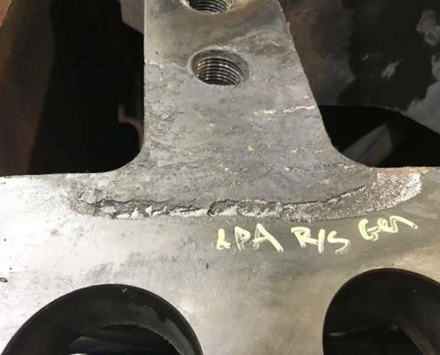
Casing Repair – Distortion and Erosion
This is Part Three of a three part Turbine Tip series, discussing the most common steam turbine casing problems: cracking, distortion and erosion.
The final Turbine Tip in this series discusses two common steam turbine casing problems – Distortion and Erosion. The repair methods employed – grinding, mechanical repair, welding and stress relief – have their own set of considerations which were covered in previous portions of the series.
Casing Distortion becomes a strong likelihood when the units accumulate operating cycles. The most common causes of distortion are steady state and transient thermal stresses which can occur within all turbine sections (HP, IP, LP). Inner casings distort more easily than outer casings due to their thinner cross-section and higher temperature differentials across the casing walls.
 6Distortion typically causes problems during disassembly and reassembly. Some examples of this are bolting interferences, gaps at the horizontal joint, galling of the fits and misalignment of the steam path seals. These problems can lead to steam leakage and rubbing. Internal leakage due to distortion reduces efficiency and power output, while leakage to atmosphere and internal rubbing can both cause a forced outage.
Water induction can cause extreme distortion of the inner cylinders. This can damage internal steam path components and lead to forced outages. Inner casings as well as valve bonnet covers can become severely warped and may require extreme measures to remove and replace.
Casing distortion can be corrected by welding, machining, localized heating and rounding discs inserted during stress relief. See previous Tips in the series for considerations in employing these methods.
Damage from erosion affects different designs at different locations, but both rotating and stationary components are vulnerable. Erosion typically takes place in the LP section where steam enthalpy drops below the saturation point. Crossover pipes and inlet areas to the LP section could increase in roughness as the surfaces wear unevenly. Support struts may thin or be cut through.
Moisture erosion can also take place in the exhaust ends of HP and IP sections if the turbine operates for long periods at low load or goes through frequent start-ups. Horizontal joints may erode and leak between stages and stationary blade support rings may erode as well as crack.
Casings, diaphragms, hoods and crossovers are usually made of carbon steel or cast iron. These materials erode approximately 20 times faster than blading material made out of 400 stainless steel.
Erosion can contribute to major damage. Repairs must be aimed at improving the erosion resistance of the steam path and support surfaces. Methods also must be examined for reducing steam moisture content and the size of droplets.
Eroded areas can be rebuilt. Stainless steel or other erosion resistant weld metal can be applied to eroded seal surfaces such as horizontal joints, flow guides and diaphragm inner and outer rings and joints. Fabricated stainless steel liners can be welded inside of crossovers, seal areas and inlet flow areas of casings. They may also be applied over support struts to protect the existing cast iron, steel or low alloy castings.
No stress relief is required in most welding applications. Epoxy or ceramic coatings may be suitable for surfaces that are not suitable for weld overlay.
For more information on your particular application, please contact us at (864) 671-1443 .
