What is a Confined Space?
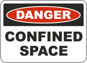
A confined space does not necessarily mean a small, enclosed space. It could be rather large, such as a ship’s hold, a fuel tank, or a pit.

One of the first defining features of a confined space is it’s large enough to allow an employee to enter and perform work. The second defining feature is it has limited means of entry or exit. Entry may be obtained through small or large openings and usually there is only one way in and out. The third defining feature is that confined spaces are not used for continuous or routine work.

All confined spaces are categorized into two main groups: non-permit and permit-required. Permit-required confined spaces must have signs posted outside stating that entry requires a permit. In general, these spaces contain serious health and safety threats including:

  • Oxygen-deficient atmospheres
  • Flammable atmospheres
  • Toxic atmospheres
  • Mechanical or physical hazards
  • Loose materials that can engulf or smother

Although a confined space is obviously dangerous, the type of danger is often hidden. For example, a confined space with sufficient oxygen might become an oxygen-deficient space once a worker begins welding or performing other tasks.

These are some of the reasons confined spaces are hazardous:

  • Lack of adequate ventilation can cause the atmosphere to become life threatening because of harmful gases.
  • The oxygen content of the air can drop below the level required for human life.
  • Sometimes a confined space is deliberately filled with nitrogen as a fire prevention technique. Nitrogen cannot sustain human life, so you must use respiratory protection.
  • Many gases are explosive and can be set off by a spark.
  • Even dust is an explosion hazard in a confined space. Finely-ground materials such as grain, fibers and plastics can explode upon ignition.
  • Confined spaces often have physical hazards, such as moving equipment and machinery.
  • Tanks and other enclosed confined spaces can suddenly be filled with materials unless the flow process for filling it is controlled.

Before entering any confined space, you must test the atmosphere to determine if any harmful gases are present. There must also be radio contact with an attendant outside the confined space and a rescue team at the ready in case of an emergency.

Don’t Kill Your Turbine on Startup

Your lube oil temperature needs to be lower at startup and shutdown than at full
speed.

Your turbine’s rotor does not actually ride on the surfaces of its bearings. It rides on a thin film of oil between the rotor and the bearing. At high turbine speeds the rotor hydroplanes across the oil, eliminating contact with the Babbit of the bearing. The heat generated by the turbine decreases the viscosity of the oil and increases its “slipperiness”, which is important at high speeds. As the rotor slows, the oil needs to be more viscous to repel the force towards the bearing.

Failure to lower the lube oil temperature (and therefore increase viscosity) can result in light bearing wipes or smearing.  These conditions would occur during turning gear operation, unit startup and unit coast down during shutdown.  The ideal lube oil temperature at these lower speeds is 90 degrees F.  Of course, oil temperature can also be too cold on startup, similar to trying to start your car on a cold winter day. Operational personnel are ultimately responsible for maintaining this lower lube oil temperature by regulating water through the lube oil coolers.

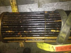
Maintaining lube oil cooler cleanliness is also very important. The tubes must be clean for efficient transfer of heat. The bundles should be cleaned every two (2) years.  Lube oil coolers are the single most common area for contaminants to hide. These contaminants can also lead to bearing failures, as discussed in an earlier Turbine Tip.

When a Backup Isn’t a Backup

The International Association of Engineering Insurers found that the highest frequency of steam turbine failures worldwide is due to loss of oil pressure. Most of these failures are caused by an unreliable backup system to maintain oil pressure to the bearings should the primary AC-driven lube oil pumps fail. These AC motors are powered by either the turbine’s output or the grid, and will fail if the turbine or generator trips, or if there is an external outage.
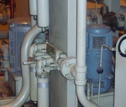
Modern turbines have backup powered DC oil pumps mounted on the oil tank which are triggered by a pressure switch in the event of a loss in oil pressure. It is very important to conduct tests with the AC and DC oil pumps during scheduled maintenance inspections to ensure that the DC pump engages as required. Such tests can be referred to as cascade pump pressure inspections. These tests will confirm the pressures when the DC oil pump will engage after the AC oil pump is actually turned off. Backup batteries should also be verified. These tests should be performed on a regular basis when the unit is down and mandatory tests should be performed before the unit is placed in operation after an overhaul.

Older turbines can use steam-driven pumps as backup. On these designs, a pressure regulator will sense the drop in bearing oil pressure and turn on the steam supply to the blade wheel of the pump. While these pumps are usually very reliable, they still must be manually tested on a regular basis and after an overhaul. Care must be taken to not overspeed the pump or it will cause internal component damage and may even completely destroy the pump.

Some older turbines use gravity lube oil tanks.  These tanks are mounted above the unit on stands and are controlled by a check valve type of arrangement.  There are no pumps involved; gravity provides the bearings with sufficient lubrication in an emergency situation. While less complicated than DC or steam powered backups, their operation must still be routinely checked.

Bottom line, a backup is not a backup unless it is reliable. And it can only be reliable if it is tested.

High Bearing Loading

Past Turbine Tips have covered the main reasons for bearings to wipe: 1) Insufficient lube oil supply, 2) Low lube oil pressure, and 3) Water in the lube oil. Every once in a while a fourth cause appears: High bearing loading.

Proper bearing loading is calculated by the elevations of the bearings, component weights and shaft alignments (bending moments, lateral, torsional). The OEM calculates the elevations and coupling alignments during the design process, based on the catenary curve (or sag chart). Calculations ofbearing loadings and alignment are usually accurate based on the design engineers’ mathematical calculations and computer model for the rotor’s geometry, speed, weight, and bearing design.

The Catenary Curve

Most of the time, high bearing loading is caused by misalignment of the turbine power train from the original design. That is, some force has moved the components from their original alignments. The source of the bearing failure can be eliminated by carefully measuring and re-aligning to the original specifications. But we have seen examples where the original calculations either were not accurate orover years of operation the bearing pedestals had moved.

Recalculating bearing loading is an arduous and potentially expensive process, so all other contributing factors should be eliminated before attempting this course. If necessary, TGM can perform the recalculation and re-alignment without the participation of the OEM. On three bearing units, it is not uncommon to utilize a dynamometer to check bearing loading during alignment and their adjustments.

Prevent Bearing Failures

TGM believes that forced outages can be avoided with proper maintenance and periodic assessments performed during a short outage. Unfortunately, we see all too many examples of too few inspections and too little maintenance.

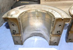
Here’s an example from one of our recent projects. The picture below is a gearbox bearing on a line shaft gearbox that had not been inspected for several years. One bearing is on one side of the bull gear and there is another just like it on the other side. As you can see, the bearing is fully wiped – it is a wonder it is still functioning. If the bearing had failed, the entire gear set would have collapsed, necessitating a compete replacement. The gear set is expensive but the real loss would be the substantial downtime for the plant as a new gear set is manufactured.

An investigation of the cause revealed very dirty oil and water in the oil but the root cause was alignment issues. We found improper spacing between the drive shaft couplings which put stress on this combination thrust and radial bearing. The increased heat from this stress led to oil degradation, made worse by the water contamination. Consequently, poor lubrication caused the bearing to wipe. Alignment issues can also be detected through vibration changes or abnormal wear patterns on the complete set of bearings. These “running assessments” are crucial to predicting problems before they cause serious damage.

It is relatively inexpensive to inspect the bearings every two years and damaged bearings can usually be replaced during the outage window. However, an incident such as overheating, abnormal vibration, or water ingress is evidence of potentially serious problems and must be addressed immediately. Any extra effort required to keep the oil clean and relatively water-free will also signal the need for an early inspection/overhaul. (See also our past Turbine Tips for maintaining the Lube Oil system and also note that re-Babbitted bearings should be UT inspected for proper bonding of the Babbitt to the shell.)

Loss of Lube Oil (Emergency Lube Oil Systems)

The International Association of Engineering Insurers found that the highest frequency of steam turbine failures worldwide is due to loss of oil. To minimize the effects of loss of oil events, all turbines have a backup or emergency oil system; however, checks of these backup systems are too often neglected. Should the backup systems be inoperable during a loss of power incident, the turbine can coast down with insufficient lubrication, causing expensive component failures. These failures can range from a loss of bearing integrity (wiped bearings) to major seal and rotating component damage, and they result in large costs to the turbine owner, not only in the repair of damage done, but in the cost of lost generation time.

Weekly maintenance checks on emergency lube oil systems should include verifying the adequacy of any battery backup system and testing the pressure switches and controllers that activate backup pumps. These tests should be performed to ensure the backup systems are fully functional should a loss of power or lube oil event occur. These simple efforts of prevention are inexpensive compared to the expenditures related to a turbine coming down without sufficient lube oil.