Inadequate Oil Supply: When a Backup isn’t a Backup

This is Part One of a three part series on steam turbine tips, discussing the challenge of inadequate oil supply.

The International Association of Engineering Insurers has found that the loss of oil pressure causes the highest frequency of failure in steam turbines worldwide. 
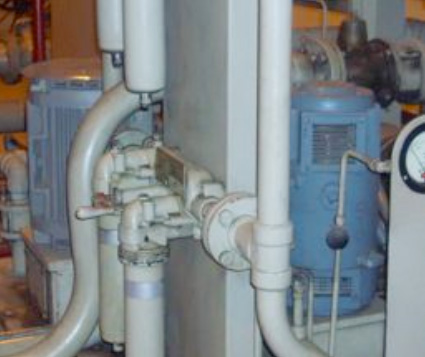
Inadequate Oil Supply - Part OneMost of these steam turbine failures are caused by an unreliable backup system to maintain oil pressure to the bearings should the primary AC-driven lube oil pumps fail. These AC motors are powered by either the turbine’s output or the grid—causing a failure if the turbine or generator trips—or if there is an external outage.

Modern turbines have backup powered DC oil pumps mounted on the oil tank, which are triggered by a pressure switch in the event of a loss in oil pressure. With this in mind, it is very important to conduct tests with the AC and DC oil pumps during scheduled maintenance inspections to ensure that the DC pump engages as required.

Such tests can be referred to as cascade pump pressure inspections.  In addition, the tests will confirm the pressures when the DC oil pump will engage after the AC oil pump is actually turned off.

Another best practice is to verify backup batteries on a regular basis, when the unit is down, and mandatory tests should be performed before the unit is placed in operation after an overhaul.

Older turbines can use steam-driven pumps as backup. On these designs, a pressure regulator will sense the drop-in bearing oil pressure and turn on the steam supply to the blade wheel of the pump.  But while these pumps are usually very reliable, they still must be manually tested on a regular basis and after an overhaul.

Care must also be taken to not overspeed the pump or it will potentially cause internal component damage and may even completely destroy the pump.

Some older turbines use gravity lube oil tanks. These tanks are mounted above the unit on stands and are controlled by a check valve type of arrangement. In such cases, there are no pumps involved—gravity provides the bearings with sufficient lubrication in an emergency situation.  While less complicated than DC or steam powered backups, their operation must still be routinely checked.

The bottom line is, that a backup is not a backup unless it is reliable. And it can only be reliable if it is tested.

Do you have questions about your steam turbine backup system? Contact PSG today to explore how we can provide support and maintenance options to help you avoid backup system problems.

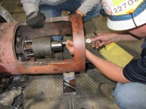
Alstom STF Steam Turbine

The Power Services Group, Inc. field service team recently completed a turnkey B-inspection on an Alstom STF steam turbine rated at 190 megawatts output. The work scope included disassembly, inspection and reassembly of the HP stop valve, HP control valve, IP stop valves, IP control valves, bearings #1 through 5, and the thrust bearing. PSG’s turnkey solution supplied outage management, technical direction, supervision, craft labor, outage tooling, consumables, non-destructive testing, and commissioning and start-up services. The project was aggressively scheduled for 10 days mechanical duration, with a two shift around the clock coverage. Completed safely and without rework, the project was one day ahead of schedule. Another great example of PSG’s expertise with Alstom steam turbines, we provide our clients with a proven and trusted alternative to the OEM.
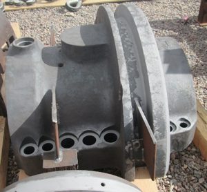
D11 Issues – Cracks in the HP/IP Shell

At STUG 2015, 50% of users of the GE D11 Steam Turbine reported cracking issues in the HP/IP shell, especially the N2 packing gland and shell fit. These cracks create the potential for forced shutdowns and relatively long outage cycle times.
Operators can mitigate this potential through a more rigorous NDE of the gland and fit any time the component is exposed, and monitoring HP/IP efficiency and/or pressure for a significant but gradual drop. This reduction may signal imminent failure and advise a shutdown of operations for a major inspection. GE indicates that the “cycle time for repairing cracked packing glands is approximately 25 days, which can become the critical path during a major outage”. This cycle time can significantly extend the OEM’s recommended 60 day plan for a major outage. GE also recommends having a spare N2 packing gland on hand if this additional cycle time will significantly disrupt operations.

TGM® recommends addressing this potential problem with a thorough and ongoing program of performance monitoring in conjunction with robust advanced planning for outages. Our Running Condition Assessment (RCA) program can help identify and evaluate this and other potential operational issues and form the cornerstone of the shutdown planning. A robust, flexible and contingent advanced plan can reduce major outage cycles from 60 days to 45 or even 30 days, depending on the amount of repair involved.

These results can only be achieved with a high level of coordination (well in advance of the outage) between the operator, the outage team, and an array of subcontractors that may (or may not) be called upon if various planned contingencies are realized. A case in point is the N2 packing gland and shell fit. Significant pre-outage planning is required to prioritize the disassembly and NDE of these components in case long-lead time issues are identified. Dust blast and NDE of the upper half of the N-2 packing case should begin as soon as it is exposed and removed; the lower half should be prioritized after the rotor is removed. A repair plan should be in place in case cracks are found, and the repair vendors should be identified, costed, and notified prior to the outage. TGM® has developed a 14 day cycle plan for most cracking issues, using pre-approved TGM®vendors. Our one-year warranty also applies to these repairs.

Most users who have experienced cracking problems have reported varied results. Repairing shell cracks involves many technical considerations and must be performed by experienced and knowledgeable personnel. Please refer to our previous 3-part series on weld repair (Part 1, Part 2, Part 3). We agree with others that once the N2 packing gland starts cracking, it will eventually have to be replaced.

TGM® additionally recommends providing on-site machining equipment in case adjustments need to be made to the packing gland or the shell fit, and for other potential modifications and known potential TIL requirements. Provisions should also be made to perform high-strength on-site weld repairs to correct dimensions or to repair shell cracks in these or other locations.

Summary
The high-efficiency GE D11 Steam Turbine is a valued workhorse in many combined cycle plants. However, the efficiency comes at the cost of many known potential problems resulting from the higher temperature and pressures, close tolerances, and overall complexity of the unit. The potential for forced shutdowns and relatively long outage cycle times can be significantly reduced. This reduction requires:

  1. A thorough and ongoing program of performance monitoring
  2. A high level of coordination (well in advance of the outage) between the operator, the outage team, and potential subcontractors to develop a robust and flexible outage plan
  3. A knowledgeable, proactive and creative program management / technical direction team to execute the many moving parts of the plan.

Please Contact Us for more information on this and other D11 issues.

Why Valve Freedom Testing is Critical

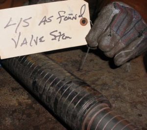
At STUG 2015, a survey revealed that 43% of D11 combined cycle users perform valve freedom testing on a daily basis, while 38% perform it on a weekly basis. The potential accumulation of deposits is a little more critical in these high temperature units, but exercising valves is important on any unit. For instance, on a recent 40MW forced outage, TGM® serviced a stuck Emergency Stop Valve that was exercised every week. How does one determine the “safe” frequency?
First a little background: We stroke valves to make sure debris and contamination have not blocked the operational clearance between the shaft and its bushing, preventing freedom of the valve to operate. A binding Main Stop Valve (MSV) in an emergency shutdown or trip could cause an overspeed condition resulting in extremely high vibration and equipment failure – even possible personal injury or death. Main steam valves should have a closing time of at least 2 seconds. Non-Return Valves (NRV) also need to be exercised on a regular basis to prevent water induction. This occurs when cooler steam condenses in the pipes and feeds back into the turbine. Water induction can cause serious damage, often referred to as a turbine rotor short condition.

Boiler chemistry plays an important role in the build up of deposits. This issue was covered in a previous Turbine Tip HERE.

In higher temperature units, there is a potential for binding of valve shafts due to exfoliation (blue blush) build-up from either the superheater tubes or reheater tubes in the boiler. Blue blush is a common problem on units that have a single axial type of design or an HP-IP type of configuration with elevated steam inlet temperatures. The HP-IP design not only affects the main steam inlet valves but the reheater valves as well. These HP-IP designs commonly operate at 1,000 degrees F inlet steam temperature at both the main steam inlet and reheater locations. This build-up of blue blush comes in from the walls of the superheater tubes or reheater tubes in the boiler and fuses onto the stems or shafts (also bushings). This exfoliation closes up the operational clearance between the shaft and its bushing, resulting in potential binding of the shaft and preventing freedom of the valve to close in an emergency shutdown or trip.

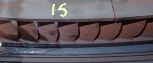
Another result of exfoliation (or any other hard particle steam contamination) is erosion
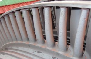
which can damage valve parts, nozzle partitions and the blading (buckets) themselves. Elevated temperatures of the steam can also cause valve shafts or stems to distort and bend, resulting in additional binding problems. With temperatures such as 1050 degrees F, creep is apt to take place more rapidly than a 1000 degree F application.

To reduce the chance of binding, OEM’s have increased the operational clearances for these high temperature machines over the design’s original upper limit. These clearances can be achieved during major inspections. Any blue blush (exfoliation) will be removed by sandblasting or by hand with emery strips (fine sandpaper grit). Stems (shafts) can be used over again and this blue blush build-up once cleaned can also be helpful in maintaining the desired clearance between shaft and bushing components.
Now we have a handle on the parameters for determining the frequency of valve freedom testing: Higher steam temperatures, current boiler chemistry, closer stem/bushing tolerances, measured stem runout, and the degree of existing blue blush build up all play a role. If production and manpower are not issues, we recommend daily freedom testing. However, if these issues are a concern, you will have to measure the risk of less frequent testing against these parameters.

If you do not feel comfortable making this decision on your own, the TGM® Running Condition Assessment (RCA) can help. The assessment looks at the condition and performance of the unit while it is running, which means there is no loss of generating capacity and the assessment is easy to schedule. We assess your boiler chemistry and blue blush build up, and consider your operating history and previous outage findings, including as-found and as-left stem/bushing clearances from previous inspections. An opinion on the frequency of valve freedom testing is but one result of the RCA. In addition, TGM® can employ an arsenal of cost-effective testing equipment and inspections to glean a wealth of information about the actual operating condition of the turbine, the generator, and all the ancillaries. TGM® analyzes this data and generates an informative report which assesses potential failure modes and weighs their effect on generating capacity and potential outage duration. Remedies and operational changes are ranked from “easy to implement with maximum benefit” to “hard to implement with minimum benefit”. Operators can then make the most informed and economically-sound maintenance decisions possible.

Click the link HERE for more information on the TGM®Running Condition Assessment.

How 0.002” Can Ruin a Turbine

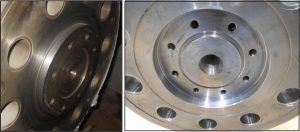
Steam turbines can reliably run for 30, 40 years or more. However everything wears and eventually fits, finishes and tolerances become unacceptable. For instance, the rabbet fit on the coupling faces of a three bearing machine will eventually become loose and in need of repair. This defect can cause misalignment, abnormal vibration levels and undue stresses on the rotors.
On a three bearing machine the contact area of the coupling faces is also referred to as the friction face. This is where the torque of the coupling bolts exerts the necessary clamping pressure to hold the coupling halves together without any movement. The normal criteria are 0.000″ to 0.001″ interference for the rabbet male to female fit. Clearance is not permitted. Once this fit becomes too loose then any kind of abnormal event, like a full load trip or synchronization of the generator out of phase could cause a small shift of position at the coupling due to the shaft torque. Since the alignment specification is one half of a mil per foot of shaft from the center of the coupling, any movement at the coupling halves can translate into a misalignment problem.

There are basically three components that need to be maintained in good condition: First is the interference fit of the male to female rabbet. We have already described the importance of this. Next is the condition of the friction faces of the coupling. The faces should maintain a surface finish of 63. They should be hand cleaned only and should never be stoned. Last but not least is the integrity of the coupling bolts.The coupling bolts can fatigue and yield over time from being loosened and re-torqued repeatedly. One should check for galls and burrs which might be evident under the bolt heads or on the flat surfaces of the nuts. The coupling bolts should be inspected nondestructively for cracks during every major inspection. All three items are simply mechanical devices which can be overlooked or assumed to be acceptable for continued service. In reality they can cause misalignment, abnormal vibration levels and undue stresses on the rotors.

Although four bearing machines do not have this particular problem, any deviation from any specification can potentially cause problems either immediately or down the road.

Overlooked Gland Seal Can Be Big Trouble

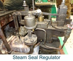
The steam turbine gland steam seal system is designed to keep steam from leaking out of the turbine and to prevent air from leaking into the turbine. A gland seal system can be as simple as a spray chamber, loop seal and a steam ejector or as complex as surface condensers, air blowers or vacuum pumps. Simple or complex, the system requires timely care and maintenance. An improperly balanced gland system can lead to water in the lubricating oil, loss of vacuum or accelerated wear on the packing gland components.
No matter the configuration of your system, there is a delicate balance between the high pressure and low pressure ends of the turbine. The labyrinth-type seal rings in the gland housings are designed for a certain amount of pressure drop which coincides with the designed operating conditions of the unit. If too much vacuum is being drawn across the seal rings premature wear and loss of vacuum will be experienced at the labyrinth seal. If too much pressure is present at the labyrinth seal then steam leakage, corrosion and premature wear will be evident.
We recommend checking the gland system for proper operation during all scheduled inspections. Corrections to the system will usually be performed during a major inspection, when all of the components are accessible. Maintenance items can include partially plugged gland leak off lines, improperly adjusted balance butterfly valves, severe wear of the spray chamber nozzle, worn out vacuum pumps, gland condenser tube leaks, eroded air blower impellers and malfunctioning steam seal regulators.
Neglect of the perceived small things can lead to bigger and more costly problems. All of the auxiliary systems that support the steam turbine are of a critical nature especially when overlooked and not properly maintained.

Steam Turbine Contamination

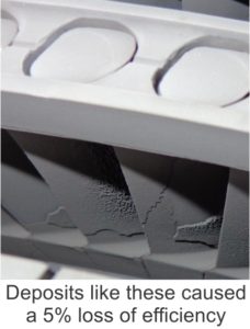
Contaminated steam can seriously impair the performance and reliability of the turbine. Dissolved minerals can cause an accumulation of deposits on surfaces, impeding fluid flow. A deposit thickness of only 3 mils on the convex surface of buckets can cause an increase of 1 to 2 % in the fuel bill and a 1% reduction in peaking capacity. (See the companion article HERE.)
Deposits can also restrict mechanical operation. A non-operating valve can allow an overspeed event. Other contaminants can induce stress corrosion cracking (SCC) which can result in catastrophic failure of components. SCC is the growth of microscopic cracks in normally ductile metals under tensile stress in a corrosive environment. SCC can be very difficult to detect. The metal surface can appear unaffected while the subsurface is filled with microscopic cracks. High-tensile structural steels, stainless steels and even mild steel can be susceptible to SCC in the presence of chloride, alkali or nitrate contamination of only a few ppm (depending on the steel and the contaminate). SCC is extremely dangerous as it can lead to disintegration of the affected part, including discs, rotors and turbine shells.

Strict monitoring of boiler chemistry can provide early detection of these contaminants. An ongoing water conditioning program can remove the contaminants before they become hazardous. A better approach is to remove the source of the contaminants.

Boiler feedwater can be a mixture of makeup from primary treatment, condensates returning from the turbine and condensates returning from process steam. Each of these can contain its own share of contaminants. A boiler can accept this feedwater and still produce steam containing less than .05 ppm of solids. However, this feedwater should never be used for attemperation as the contaminates will be introduced straight to the turbine. Water for attemperation should be close to distillate quality.

Dissolved solids from boiler chemicals should be separated from the steam before it leaves the drum. Operating the boiler with too much water in the drum, or with foaming or priming in the boiler, will introduce too much water into the steam separator and reduce its efficiency. Efficient separators can approach less than .01 ppm of solids in the steam. Dissolved gases such as ammonia or CO2 cannot be separated and must be controlled in the boiler water.

Condensates can be contaminated by leaks in the heat exchangers used for process steam, or even incorrect piping of the chemical feed system. One should suspect process chemical leaks if organic, sulfide, ammonia, amine or copper contaminants are detected. Suspect leaks in the chemical feed system for the drum if excess OH alkalinity or phosphate is detected.

Extreme care should be exercised when using volatile acids (such as hydrochloric acid) when cleaning the the condenser. Acid fumes entering low pressure areas of the turbine can condense in confined areas such as blade roots and cause stress corrosion. The proper procedure is to close the joint between the condenser and the low pressure areas with plastic or fabric to form a vapor barrier. All remaining acid should be neutralized and removed from surfaces.

Contamination can also be introduced during inspection and repair of a turbine. Manufacturing fluids, lubricants and preservatives can contain sulfur or chlorine which can decompose into acids. Machined areas and replacement parts should be cleaned with solvents (such as denatured alcohol) and then dried off. NDE/NDT chemicals, especially the dye penetrant Zyglo, can also decompose into acids. Parts inspected with these methods should also be solvent cleaned and dried. Environmental pollutants can introduce solids (dirt) and acid forming compounds. Exposed turbine steam path components should be protected by plastic or cloth until reassembled.

Potential turbine contamination by either deposits or acids should be addressed as soon as it is suspected. Several methods for confirmation and ameliorization are available, depending on the type and degree of the contaminant.

Please contact Mr. Turbine® for advice if you suspect or encounter turbine contamination.

Casing Repair – Part 3: Distortion & Erosion

The final Turbine Generator Tip in this series discusses two common steam turbine casing problems – Distortion and Erosion. The repair methods employed – grinding, mechanical repair, welding and stress relief – have their own set of considerations which were covered in previous portions of the series.
Casing Distortion
Casing Distortion becomes a strong likelihood when the units accumulate operating cycles. The most common causes of distortion are steady state and transient thermal stresses which can occur within all turbine sections (HP, IP, LP). Inner casings distort more easily than outer casings due to their thinner cross-section and higher temperature differentials across the casing walls. Distortion typically causes problems during disassembly and reassembly. Some examples of this are bolting interferences, gaps at the horizontal joint, galling of the fits and misalignment of the steam path seals. These problems can lead to steam leakage and rubbing. Internal leakage due to distortion reduces efficiency and power output, while leakage to atmosphere and internal rubbing can both cause a forced outage.
Water induction can cause extreme distortion of the inner cylinders. This can damage internal steam path components and lead to forced outages. Inner casings as well as valve bonnet covers can become severely warped and may require extreme measures to remove and replace.
Casing distortion can be corrected by welding, machining, localized heating and rounding discs inserted during stress relief. See previous Tips in the series for considerations in employing these methods.

Erosion
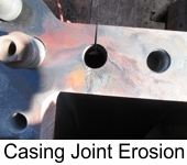
Damage from erosion affects different designs at different locations, but both rotating and stationary components are vulnerable. Erosion typically takes place in the LP section where steam enthalpy drops below the saturation point. Crossover pipes and inlet areas to the LP section could increase in roughness as the surfaces wear unevenly. Support struts may thin or be cut through. Moisture erosion can also take place in the exhaust ends of HP and IP sections if the turbine operates for long periods at low load or goes through frequent start-ups. Horizontal joints may erode and leak between stages and stationary blade support rings may erode as well as crack.
Casings, diagrams, hoods and crossovers are usually made of carbon steel or cast iron. These materials erode approximately 20 times faster than blading material made out of 400 stainless steel.
Erosion can contributes to major damage. Repairs must be aimed at improving the erosion resistance of the steam path and support surfaces. Methods also must be examined for reducing steam moisture content and the size of droplets.
Eroded areas can be rebuilt. Stainless steel or other erosion resistant weld metal can be applied to eroded seal surfaces such as horizontal joints, flow guides and diaphragm inner and outer rings and joints. Fabricated stainless steel liners can be welded inside of crossovers, seal areas and inlet flow areas of casings. They may also be applied over support struts to protect the existing cast iron, steel or low alloy castings. No stress relief is required in most welding applications. Epoxy or ceramic coatings may be suitable for surfaces that are not suitable for weld overlay.
For more information on your particular application, please contact Mr. Turbine®.

Casing Repair – Part 2: Welding Considerations

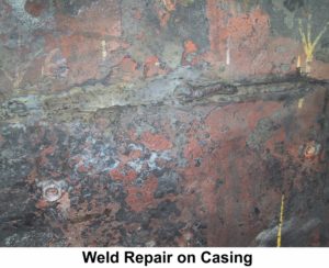
Welding is a common method to repair turbine casing cracks, but it must be applied with consideration. Most turbine casing alloys can be welded using either of two distinct procedures: stress relieved and non-stress relieved. The procedure selected is often dictated by time and cost restraints.
Non-stress relieved welds have the advantage of lower cost and shorter outage time. The disadvantage is that the weld can be short lived. The procedure follows this outline: A preheat of about 500 degree F or greater is used. A shielded metal arc weld is performed with a non-matching high nickel content filler. This use of dissimilar metals as filler can lead to low cycle metal fatigue. No post-weld stress relief is performed but the preheat conditions are maintained throughout the process.

Stress relieved welding offers the best potential for a long repair life, but is complicated and time consuming. The procedure follows this outline: A lower preheat of about 300 degree F is used. A shielded metal arc or metal inert gas weld is performed with a matching metal content filler. The casing is then placed in a furnace and raised to a temperature of over 1,000 degrees F. The exact temperature depends on the alloy, the procedure and the application. Much higher temperatures may be required. There are no problems with differential expansion during turbine operation since the weld uses matching filler metal.

The pre-weld residual stress levels in the casing must be carefully assessed to increase the probability of a successful weld. The high levels of residual stresses in the casing can combine with the added stresses of welding to cause uncontrolled distortion and hot cracking during the stress relief phase. Residual stresses generated by the weld passes can be reduced through techniques such as grinding, peening between passes, and peening and grinding. Therefore, the welding procedure must be performed by a skilled contractor.

The best way to control distortion during stress relief is to bolt the casing halves together and place the assembly in the furnace. This would be most applicable to an inner casing that can be easily removed from its outer casing. If only the upper half of the casing is going to be repaired, a thick plate can be bolted onto the horizontal joint as a substitute for the lower case. Distortion can be further controlled by inserting custom fabricated rounding rings or disks into the assembly before thoroughly bolting it together.

If the facility has ample room, a portable furnace can be built on-site. Otherwise, the assembly must be sent out for this process. If the assembly is too large for the furnace, stress relief can be done on a local area of the case, allowing suitable temperature gradients away from the weld areas. Whatever the location, the temperature of the furnace and the assembly must be stringently monitored during the entire stress relief process. Multiple heat cycles and possible re tightening of the joint bolting between cycles may be necessary. This is a process which has been refined over the years and continues to get better. Again, it is always a good practice to perform an assessment prior to performing any of the above procedures.

The next Turbine Generator Tip in the series discusses casing distortion and erosion problems. For more information on your particular application, please contact Mr. Turbine®.

Casing Repairs (Part 1: Cracking)

This three part Turbine Generator Tip discusses the most common steam turbine casing problems: cracking, distortion and erosion. Most units can be repaired by grinding, welding or by pre-stressed mechanical methods. Finite element calculations show that in many cases, repairs can overcome some of the original design weaknesses and extend useful life by up to 20 years. But before proceeding with a repair, understand the mechanisms of both the casing damage and the proposed repair. Improper repair can be useless or worse.
Cracking is the most common problem on utility units built before 1970. Cracking typically occurs at the steam inlet areas on the HP and IP sections, where transient thermal stresses can exceed the yield point of the casing material. Cracking may be found on the interior surfaces of steam chests, valve bodies, nozzle chambers, seal casings, diaphragm fits and bolt holes. In the low pressure section (LP) cracking can also occur at the inlet sections, inner casings, support struts, bolt holes and diaphragm fits. Computer modeling and advanced alloys have reduced the likelihood of cracking in more modern units, but cracks can develop in any unit, especially those experiencing more stop/start cycles.
Every crack must be fully analyzed before attempting repairs. NDE inspection must be performed at a minimum. Radiograph inspections may provide greater assurance by revealing the extent of the crack in relation to its location and the thickness of the surrounding area. Some OEM’s have a detailed customer letter on known areas of potential cracking, their particular process to map out these cracks, and the proposed corrective action and potential life expectancy.
Although grinding is a common repair method, it can increase the potential for new cracks if improperly applied. Cracks in steam chests can potentially expand, making repairs more costly. Grinding on cracks in older machines may open up hidden voids in the casing, making the condition much worse. Another problem is that even when an NDE shows that cracks have been removed by grinding, very small undetectable cracks may still be present and may lead to future larger cracks.
Welding of cracks is another common repair method. There are two distinct procedures for welding: stress relieved and non-stress relieved. Non-stress relieved weld repair has the advantage of shorter outage duration but can fail much sooner than a stress relieved weld. This complicated topic will be discussed in our next Turbine Generator Tip in the series.
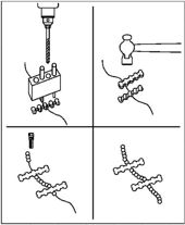
Mechanical Repairs can be applied to cracks, but must be properly designed to redistribute tensile loading away from the crack area. One method is to apply stitches. Metal inserts are placed across or along the crack and drilled and pinned to the case (see picture). Another method is to place bars or dog bone shapes across previously ground out areas. A more effective version of this method uses precision machining and the application of a lobe-lock designed through finite element analysis. The material used must provide adequate load properties and must be ductile at all temperatures to prevent cracking of the lobe-lock.
Mechanical repairs have several advantages. The repairs can be performed in place, with no possibility of casing distortion because there is no heating or welding. Machining durations are shorter and easier to quantify. These repairs can also extend life to the area (vs. welding). Disadvantages are that the mechanical repair is conducted on a low cycle fatigue crack and concentrated in an area surrounded by non-cracked material.

The next Turbine Generator Tip in the series discusses stress relieved vs. non-stress relieved welding. For more information on your particular application, please contact Mr. Turbine®.