 At STUG 2015, a survey revealed that 43% of D11 combined cycle users perform valve freedom testing on a daily basis, while 38% perform it on a weekly basis. The potential accumulation of deposits is a little more critical in these high temperature units, but exercising valves is important on any unit. For instance, on a recent 40MW forced outage, TGM® serviced a stuck Emergency Stop Valve that was exercised every week. How does one determine the “safe” frequency?
First a little background: We stroke valves to make sure debris and contamination have not blocked the operational clearance between the shaft and its bushing, preventing freedom of the valve to operate. A binding Main Stop Valve (MSV) in an emergency shutdown or trip could cause an overspeed condition resulting in extremely high vibration and equipment failure – even possible personal injury or death. Main steam valves should have a closing time of at least 2 seconds. Non-Return Valves (NRV) also need to be exercised on a regular basis to prevent water induction. This occurs when cooler steam condenses in the pipes and feeds back into the turbine. Water induction can cause serious damage, often referred to as a turbine rotor short condition.
Boiler chemistry plays an important role in the build up of deposits. This issue was covered in a previous Turbine Tip HERE.
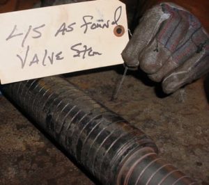
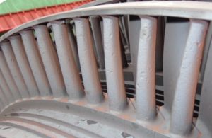
In higher temperature units, there is a potential for binding of valve shafts due to exfoliation (blue blush) build-up from either the superheater tubes or reheater tubes in the boiler. Blue blush is a common problem on units that have a single axial type of design or an HP-IP type of configuration with elevated steam inlet temperatures. The HP-IP design not only affects the main steam inlet valves but the reheater valves as well. These HP-IP designs commonly operate at 1,000 degrees F inlet steam temperature at both the main steam inlet and reheater locations. This build-up of blue blush comes in from the walls of the superheater tubes or reheater tubes in the boiler and fuses onto the stems or shafts (also bushings). This exfoliation closes up the operational clearance between the shaft and its bushing, resulting in potential binding of the shaft and preventing freedom of the valve to close in an emergency shutdown or trip.
 Another result of exfoliation (or any other hard particle steam contamination) is erosion
which can damage valve parts, nozzle partitions and the blading (buckets) themselves. Elevated temperatures of the steam can also cause valve shafts or stems to distort and bend, resulting in additional binding problems. With temperatures such as 1050 degrees F, creep is apt to take place more rapidly than a 1000 degree F application.
 To reduce the chance of binding, OEM’s have increased the operational clearances for these high temperature machines over the design’s original upper limit. These clearances can be achieved during major inspections. Any blue blush (exfoliation) will be removed by sandblasting or by hand with emery strips (fine sandpaper grit). Stems (shafts) can be used over again and this blue blush build-up once cleaned can also be helpful in maintaining the desired clearance between shaft and bushing components.
Now we have a handle on the parameters for determining the frequency of valve freedom testing: Higher steam temperatures, current boiler chemistry, closer stem/bushing tolerances, measured stem runout, and the degree of existing blue blush build up all play a role. If production and manpower are not issues, we recommend daily freedom testing. However, if these issues are a concern, you will have to measure the risk of less frequent testing against these parameters.
If you do not feel comfortable making this decision on your own, the TGM® Running Condition Assessment (RCA) can help. The assessment looks at the condition and performance of the unit while it is running, which means there is no loss of generating capacity and the assessment is easy to schedule. We assess your boiler chemistry and blue blush build up, and consider your operating history and previous outage findings, including as-found and as-left stem/bushing clearances from previous inspections. An opinion on the frequency of valve freedom testing is but one result of the RCA. In addition, TGM® can employ an arsenal of cost-effective testing equipment and inspections to glean a wealth of information about the actual operating condition of the turbine, the generator, and all the ancillaries. TGM® analyzes this data and generates an informative report which assesses potential failure modes and weighs their effect on generating capacity and potential outage duration. Remedies and operational changes are ranked from “easy to implement with maximum benefit” to “hard to implement with minimum benefit”. Operators can then make the most informed and economically-sound maintenance decisions possible.
Click the link HERE for more information on the TGM®Running Condition Assessment.

Why Valve Freedom Testing is Critical
/in Steam Turbine Tips /by Mike.LakeFirst a little background: We stroke valves to make sure debris and contamination have not blocked the operational clearance between the shaft and its bushing, preventing freedom of the valve to operate. A binding Main Stop Valve (MSV) in an emergency shutdown or trip could cause an overspeed condition resulting in extremely high vibration and equipment failure – even possible personal injury or death. Main steam valves should have a closing time of at least 2 seconds. Non-Return Valves (NRV) also need to be exercised on a regular basis to prevent water induction. This occurs when cooler steam condenses in the pipes and feeds back into the turbine. Water induction can cause serious damage, often referred to as a turbine rotor short condition.
Boiler chemistry plays an important role in the build up of deposits. This issue was covered in a previous Turbine Tip HERE.
In higher temperature units, there is a potential for binding of valve shafts due to exfoliation (blue blush) build-up from either the superheater tubes or reheater tubes in the boiler. Blue blush is a common problem on units that have a single axial type of design or an HP-IP type of configuration with elevated steam inlet temperatures. The HP-IP design not only affects the main steam inlet valves but the reheater valves as well. These HP-IP designs commonly operate at 1,000 degrees F inlet steam temperature at both the main steam inlet and reheater locations. This build-up of blue blush comes in from the walls of the superheater tubes or reheater tubes in the boiler and fuses onto the stems or shafts (also bushings). This exfoliation closes up the operational clearance between the shaft and its bushing, resulting in potential binding of the shaft and preventing freedom of the valve to close in an emergency shutdown or trip.
which can damage valve parts, nozzle partitions and the blading (buckets) themselves. Elevated temperatures of the steam can also cause valve shafts or stems to distort and bend, resulting in additional binding problems. With temperatures such as 1050 degrees F, creep is apt to take place more rapidly than a 1000 degree F application.
Now we have a handle on the parameters for determining the frequency of valve freedom testing: Higher steam temperatures, current boiler chemistry, closer stem/bushing tolerances, measured stem runout, and the degree of existing blue blush build up all play a role. If production and manpower are not issues, we recommend daily freedom testing. However, if these issues are a concern, you will have to measure the risk of less frequent testing against these parameters.
If you do not feel comfortable making this decision on your own, the TGM® Running Condition Assessment (RCA) can help. The assessment looks at the condition and performance of the unit while it is running, which means there is no loss of generating capacity and the assessment is easy to schedule. We assess your boiler chemistry and blue blush build up, and consider your operating history and previous outage findings, including as-found and as-left stem/bushing clearances from previous inspections. An opinion on the frequency of valve freedom testing is but one result of the RCA. In addition, TGM® can employ an arsenal of cost-effective testing equipment and inspections to glean a wealth of information about the actual operating condition of the turbine, the generator, and all the ancillaries. TGM® analyzes this data and generates an informative report which assesses potential failure modes and weighs their effect on generating capacity and potential outage duration. Remedies and operational changes are ranked from “easy to implement with maximum benefit” to “hard to implement with minimum benefit”. Operators can then make the most informed and economically-sound maintenance decisions possible.
Click the link HERE for more information on the TGM®Running Condition Assessment.
Why is a Clean Generator a Happy Generator?
/in Generator Tips /by Mike.LakeThe two most common and virulent contaminates are water and oil. Each of these two materials act as an adhesive that binds particulates into a buildup across surfaces throughout a generator. This is especially true of air-cooled machines. Also, water is a conductor of electricity. The ramifications of its presence need no explanation.
Oil contamination is undesirable for two additional reasons. First, it is a lubricant. Electrical windings, and in particular stator windings, are held tightly together through a number of frictional forces. Side packing holds the stator windings tightly within the stator slots side-to-side. The wedge system holds the stator windings radially within the same slots. Hundreds of blocks and miles of lacing secure the stator end windings to one another as well as to surge rings and brackets. Oil contamination leaches in between all these components. Its lubricating qualities facilitates looseness and mechanical fretting. Second, oil is a mild solvent. Over time it will break down the organic binders in paints, varnishes, and even modern epoxies. Degradation of these materials reduces the dielectric strength of the ground wall insulation system and accelerates electrical aging. Oil’s solvent and lubrication properties contribute to mechanical aging by impairing the homogeneous and monolithic character of the stator winding. Oil contamination must be eliminated (to the best degree possible) to ensure the long-term serviceability of a generator. More importantly, the source of the leakage must be remediated.
Opinions vary regarding proper cleaning materials and methodologies. However, it should be considered as best practice to define a cleaning protocol based upon: 1) Type of contamination; 2) Degree of contamination; 3) Type of insulation system, and; 4) Condition/disposition of the insulation system. Cleaning may include simple wipe down, solvent spraying, dry ice blasting, dry media blasting (corn cob, walnut shell, etc.), steam cleaning, or some combination. Positives and negatives are associated with each and should be discussed prior to implementation.
Simply stated, a clean generator is a happy generator. A consistently clean generator runs cooler, stays mechanically-robust longer, and is significantly less prone to electrical tracking and flash-over failure. A clean generator demonstrates superior operation and maintenance practices and helps assure quality service life. How clean is your generator?
How 0.002” Can Ruin a Turbine
/in Steam Turbine Tips /by Mike.LakeOn a three bearing machine the contact area of the coupling faces is also referred to as the friction face. This is where the torque of the coupling bolts exerts the necessary clamping pressure to hold the coupling halves together without any movement. The normal criteria are 0.000″ to 0.001″ interference for the rabbet male to female fit. Clearance is not permitted. Once this fit becomes too loose then any kind of abnormal event, like a full load trip or synchronization of the generator out of phase could cause a small shift of position at the coupling due to the shaft torque. Since the alignment specification is one half of a mil per foot of shaft from the center of the coupling, any movement at the coupling halves can translate into a misalignment problem.
There are basically three components that need to be maintained in good condition: First is the interference fit of the male to female rabbet. We have already described the importance of this. Next is the condition of the friction faces of the coupling. The faces should maintain a surface finish of 63. They should be hand cleaned only and should never be stoned. Last but not least is the integrity of the coupling bolts.The coupling bolts can fatigue and yield over time from being loosened and re-torqued repeatedly. One should check for galls and burrs which might be evident under the bolt heads or on the flat surfaces of the nuts. The coupling bolts should be inspected nondestructively for cracks during every major inspection. All three items are simply mechanical devices which can be overlooked or assumed to be acceptable for continued service. In reality they can cause misalignment, abnormal vibration levels and undue stresses on the rotors.
Although four bearing machines do not have this particular problem, any deviation from any specification can potentially cause problems either immediately or down the road.
Why Use Hydrogen to Cool a Generator?
/in Generator Tips /by Mike.LakeHydrogen was first proposed as a cooling media for rotating electrical machinery in 1925. The first hydrogen-cooled machine, a 12.5 MVA synchronous condenser, was placed into service in 1928. Nearly a decade later, in 1937, the first hydrogen-cooled turbo generator was commission by Dayton Power and Light in Dayton, Ohio – a General Electric 31.25 MVA, 3,600 RPM unit. Coincidently, this was the very same year that the German passenger zeppelin, Hindenburg, met with its fiery demise.
So why use hydrogen to cool a generator? Despite its reputation, hydrogen gas has qualities that make it a superior heat transfer media and internal atmosphere for a generator. Hydrogen is much less dense that air. Cooling fans can move up to fourteen (14) times as much hydrogen as air using the same amount of power. Combine this with the fact that hydrogen conducts seven (7) times more heat than air. At the same time, hydrogen has a higher heat transfer coefficient; meaning it is better at picking up heat from a hot surface. Hydrogen also has approximately the same specific heat characteristic as air, since they both can carry about the same amount of heat.
Hydrogen does not support combustion. It only becomes volatile when mixed with air. What makes the mixture so deadly is the breadth of its explosive range – from as little as 4-percent to as much as 74-percent. The potential energy release from a hydrogen-fueled explosion is enormous:
Due to the volatility of hydrogen gas, the power generation industry employs tried and true procedures for its monitoring, handling, and disposition. Fires and explosions do occur, though their frequency is miniscule in comparison to the sheer number of hydrogen-cooled generators in operation and the vast quantities of hydrogen handled on an annual basis. The positives far outnumber the negatives. Hydrogen has been an internal cooling media of choice for the last eighty years and will continue to be so for the foreseeable future.
Safely Check for Gas Turbine Fuel/Air Leaks
/in Combustion Turbine Tips /by Mike.LakeSince this a relatively simple and safe procedure TGM® recommends performing this check prior to any maintenance being performed (after the unit is shut down and just before the LOTO is initiated). Any and all air leaks can be identified and they can be addressed during the scheduled maintenance cycle if feasible.
There have been several TIL’s released on the care and quality of the flexible metal hoses for CT’s. The end user has gotten into the practice of having the flexible metal hose pressure checked during the hot gas path cycle. If the soapy water checks are performed prior to any work being performed and any of the flexible metal hoses are leaking then why bother to have them pressure checked. This approach can save expensive labor cost by eliminating a test on a hose that will fall out. Plus wouldn’t it be better to know you have a leak at the wrapper four way joint before it is removed to perform a hot gas path than finding out during the inspection at start up?
Why is a Stator Core Made of Laminated Steel?
/in Generator Tips /by Mike.LakeStator core laminations have a very specific profile and the dimensions have exacting tolerances. Currently, laminations are manufactured by Punching/stamping dies, or Computer-controlled laser cutting machines.
An energized turbine generator rotor creates an electromagnetic field with lines of force traveling from north pole to south pole very much like that of planet Earth.
This same principle applies in other applications. Anyone who has used a common induction bearing heater will have noticed that the cross bar is fabricated of laminated (and insulated) steel. During the process of induction heating, the bearing heats up quite quickly while the cross bar stays relatively cool.
Simply stated a stator core is laminated and insulated in order to reduce induced circulating currents and associated heat down to a manageable level.
Overlooked Gland Seal Can Be Big Trouble
/in Steam Turbine Tips /by Mike.LakeNo matter the configuration of your system, there is a delicate balance between the high pressure and low pressure ends of the turbine. The labyrinth-type seal rings in the gland housings are designed for a certain amount of pressure drop which coincides with the designed operating conditions of the unit. If too much vacuum is being drawn across the seal rings premature wear and loss of vacuum will be experienced at the labyrinth seal. If too much pressure is present at the labyrinth seal then steam leakage, corrosion and premature wear will be evident.
We recommend checking the gland system for proper operation during all scheduled inspections. Corrections to the system will usually be performed during a major inspection, when all of the components are accessible. Maintenance items can include partially plugged gland leak off lines, improperly adjusted balance butterfly valves, severe wear of the spray chamber nozzle, worn out vacuum pumps, gland condenser tube leaks, eroded air blower impellers and malfunctioning steam seal regulators.
Neglect of the perceived small things can lead to bigger and more costly problems. All of the auxiliary systems that support the steam turbine are of a critical nature especially when overlooked and not properly maintained.
Compressor Failures – Stator Vane Lock-up
/in Combustion Turbine Tips /by Mike.LakeSome compressor failures have been attributed to “lock-up” of the stator vanes. The vane roots are designed to rock slightly at their roots when moved with your hand. Rust and debris can inhibit this movement. An immobile vane changes the stress profile on the vane which can cause cracking and potential failure. Mechanics should check for proper movement at each inspection.
Removing locked-up stator vanes has been a challenge for service providers. The OEM has come up with material upgrades to address the corrosion problems in these areas. The compressor upgrades are designed to reduce the potential for compressor failures and lock-up of the stator vanes. Some providers use destructive methods to cut out the vanes, potentially damaging the compressor casing. The OEM recommends the use of their (expensive) special tooling to reduce and hopefully prevent casing damage. An alternate method that TGM®has used very successfully is a process of heating and quenching. Heating the locked-up stator vane segments with a torch and quickly quenching the vane with cold water will typically free the vane segment for removal without damaging the casing. The process of heating and quenching (applied by an experienced team) can save time and money while reducing and hopefully eliminating damage to the compressor casing. TGM® can provide its expertise in removing stubborn stator vane segments and, if needed, quickly replace damaged stator vanes to get the customer back on line as soon as possible.
TGM®‘s experienced combustion turbine Technical Directors and crews often delight customers by providing innovative methods that can efficiently and permanently solve issues and get the customer back on line to make power. Early detection of shim migration and stator vane problems can be performed by TGM®through borescope inspections and eddy current NDE.
TGM®‘s comprehensive borescope diagnostics can provide recommendations and solutions to address many other compressor issues. Contact Us to find out how we can help.
Safety and Hand Grenades
/in Safety Tips /by Mike.LakeOur mechanics were using a striking wrench to loosen bolts on a turbine. One mechanic held a rope attached to the end of the wrench in order to apply a slight torque to keep the wrench seated on the nut. Another mechanic struck the wrench with an 8 pound hammer. Naturally, the holder of the rope is standing along the path of the hammer swing. The rope is normally long enough to position the mechanic well outside the hammer’s path. In this recent case, space was tight and the rope was too short. No problem if every hammer blow strikes the wrench. The mechanic was confident, declaring “I never miss!”. Except he did, and struck his partner in his safety glasses. His partner suffered a slight cut from the glasses but was
otherwise OK. (See adjacent picture.)
Our solution is a specialized tool which allows a mechanic to stand perpendicular to the path of the hammer blow while holding the striking wrench. The picture at the top of the article shows a mechanic setting the wrench on a nut. He will get out of the way after another mechanic grabs the end of the tool. A second mechanic will strike the wrench. An added benefit is that the wrench will not go flying if it is dislodged from the nut.
Hydraulic wrenches are also used to remove nuts in close quarters. TGM® uses this tool where warranted. Hydraulic wrench manufacturers maintain explicit warnings regarding their use and require operators to have specialized training. The hydraulic sockets can shatter even when used properly. We have experienced several Near Miss incidents in their use, and have discussed the dangers in several other Turbine Tips. (See below).
Please Contact Us if you would like more information on procuring or using any of these tools.
Protect your turbine with a good coat
/in Combustion Turbine Tips /by Mike.LakeTBCs are designed to reduce the temperature of the buckets and stators while providing resistance to corrosion and reducing oxidation of the component. TBCs form aluminum-oxide and chromium-oxide scales and act as a physical barrier to reduce component temperatures, extending the life of the parts. These TBCs are subjected to mechanical stresses, and spallation (coating separation) can occur. If a significant amount of TBC has separated from the metal, the parent metal will be exposed to the hot combustion gases and component degradation will be accelerated.
Hot gas path components should be inspected for TBC spallation at every Hot Gas Path or Major outage. Streaks of brown lines that appear to be coming from the cooling holes are a good sign that the component is receiving adequate cooling air, and spallation is at a minimum. When receiving components from the repair shop it is important to carefully inspect the components for an even coat of TBC. Also inspect the cooling air passages for debris and proper sizing to ensure that proper air flow can pass through the tiny passages for designed cooling.